Drawing GT2 Belts in CAD, and a common Reducer Design Pattern
CAD from the example in this post is here. or, hit the download below:
It’s really common that we want to boost the torque coming from a motor - though we trade top speed for the added Nm or lb-in, most machine applications go “slowly” relative an electric motor’s top RPM. Probably about the simplest way to do this is with a small belt reduction.
Since they’ve become ubiquitous, GT2 belts are my part-of-choice here, and they’re commonly available in “closed” lengths of ~ 200mm, 280mm … through to around 600mm. Mostly, these can be found in 6mm widths, but if you get fancy with a supplier like SDP-SI you can get them in 9 or 15mm widths as well.
There’s a danger of becoming like-a-cooking-blog post here: just get to the GD recipe, right?
Drawing GT2 Pulleys in CAD
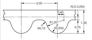
There’s the profile, which we can draw in CAD… exactly as you would expect. This wraps well around a circle as well. I.E. in the sketch below, the outer circle is the pitch diameter of the pulley we’re trying to draw, i.e. the dashed line in the GT2 diagram.
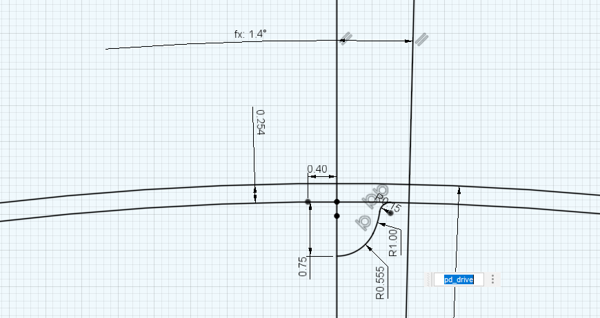
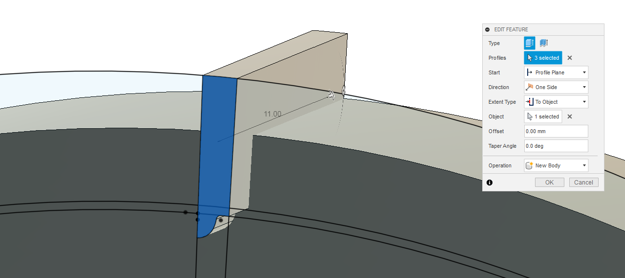
I always draw one half-tooth and then extrude it, here I’m extruding the negative space of the profile, i.e. the part the belt occupies, and I’m going to diff that from the solid block of pulley which I have previously modelled.
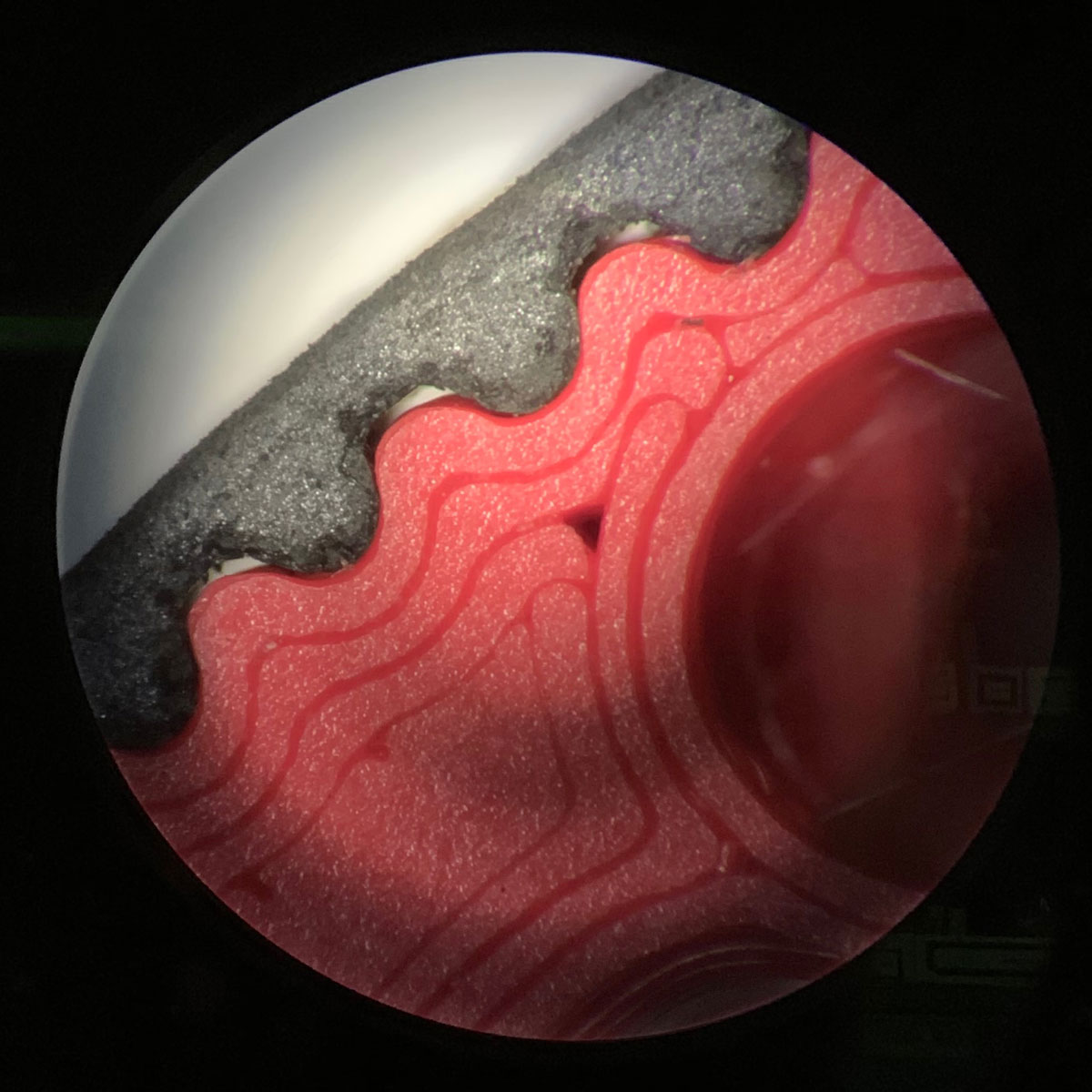
There’s one nuance here: the tooth’s peak is just around the minimum feature size on many FDM 3D Printers, i.e. here’s a part like this printed with dead-reckoned geometry (i.e. no adjustments to the tooth profile):
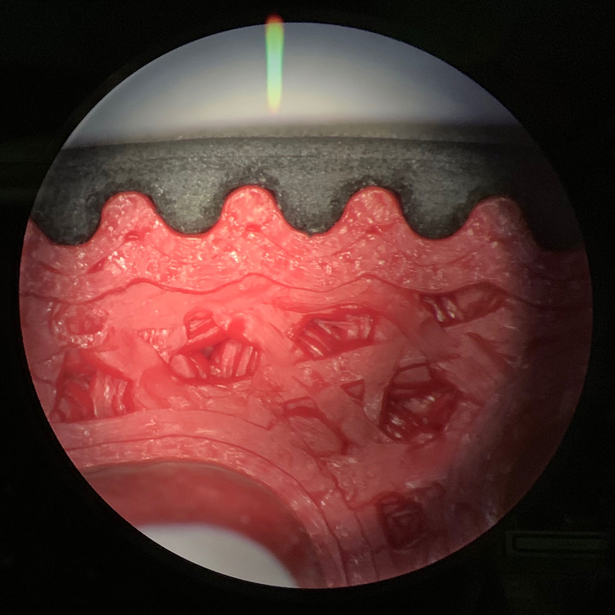
This is not quite good enough… so I use an offset step, pushing the peak of the teeth up by 0.05mm.
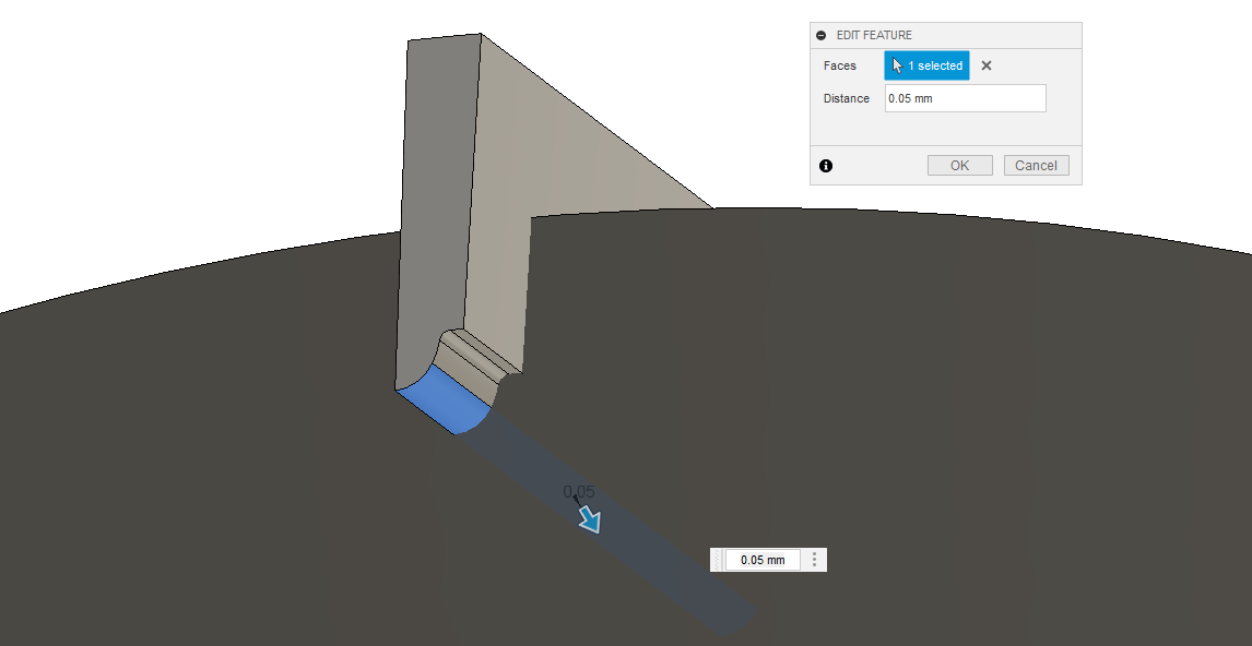
This way, I get the tooth-peaks just hitting the trough of the belt-peaks… as below. This tight fit allows us to transmit more torque before the belt skips a tooth.
To note: I also print these with a few careful settings:
- check
external perimeters firstinlayers and perimiterssettings - exterior perimeters should be printed very slowly, like 10mm/sec
- small layer heights (0.1mm) are best for teeth
This means that toothed-parts often print very slowly, but the quality of the fit is important for performance.
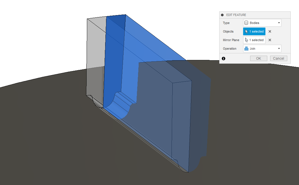
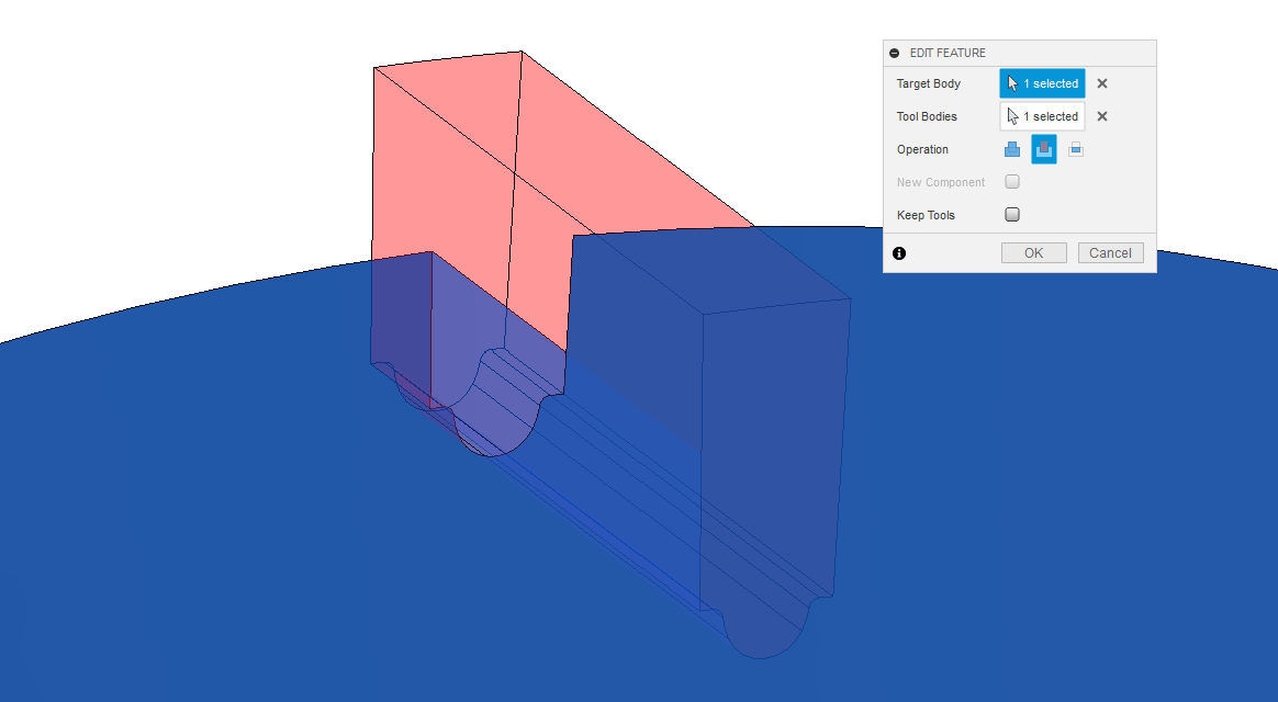
To carry on with the modelling, we can mirror this thing and then boolean it out of the pulley mass:
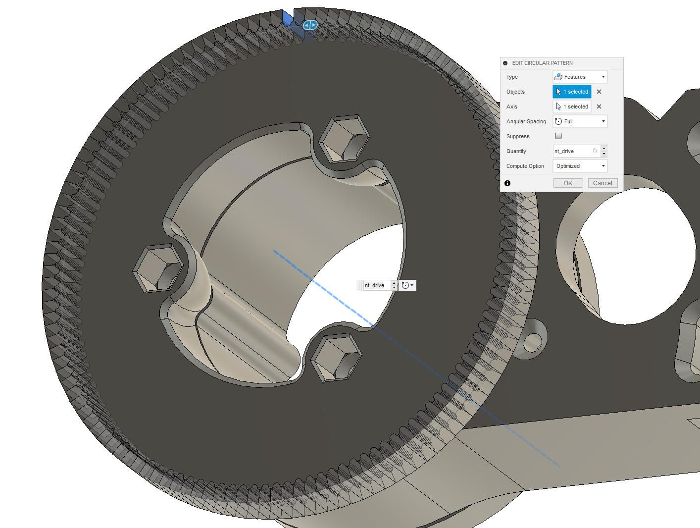
And use a repeating pattern (repeating the feature of the boolean) to carry that around the circumference of the pulley:
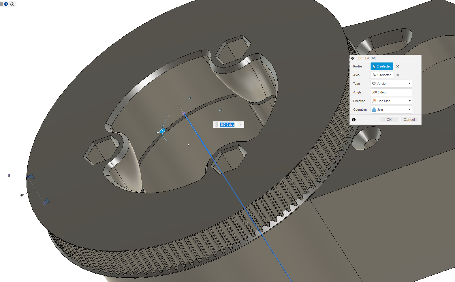
I also revolve a little flange back on these things:
We’ve got our part. Nice.
The Rest of the Rotary Drive
Now - this is just a design pattern that I use all over the place, and I suspect if you’re reading here, you’ve some particular application in mind as well: a rotary positioning stage - maybe the 4th axis of a small CNC - or a tool-changer carousel, or a plain reduction to a second belt drive, who knows. In many of these cases we also of course want to mount the motor, tension the belt, and support the pulley.
I’ve this CAD here for the rest of it, and there’s a few more tricks to share:
Trick #1: Belt Length
In most cases, we have a fixed belt length (i.e. I keep stock of 200 and 280mm long belts), but can vary other geometries. To tune my CAD so that the belt will be nearly in tension before we tension it (i.e. to get the motor-to-rotary-shaft-distance in the right ballpark), we have this formula:
belt_length = 2 * center_distance + 1.57 * ( pitch_diameter_drive + pitch_diameter_pinion ) + ( ( pitch_diameter_drive - pitch_diameter_pinion ) ^ 2 ) / ( 4 * center_distance )
It’s a little bonkers, I know. I should also note that this is an approximation… and I actually have forgotten where I originally found it. It also seems strange that we would calculate the belt length, and then fiddle the center distance: this is a little bit of a style thing: I like to i.e. design a center distance such that the calculated belt_length is just under the actual length, meaning it will be on the tighter side of the fit. If you’d like to flip the relationships, the algebra is yours to do.
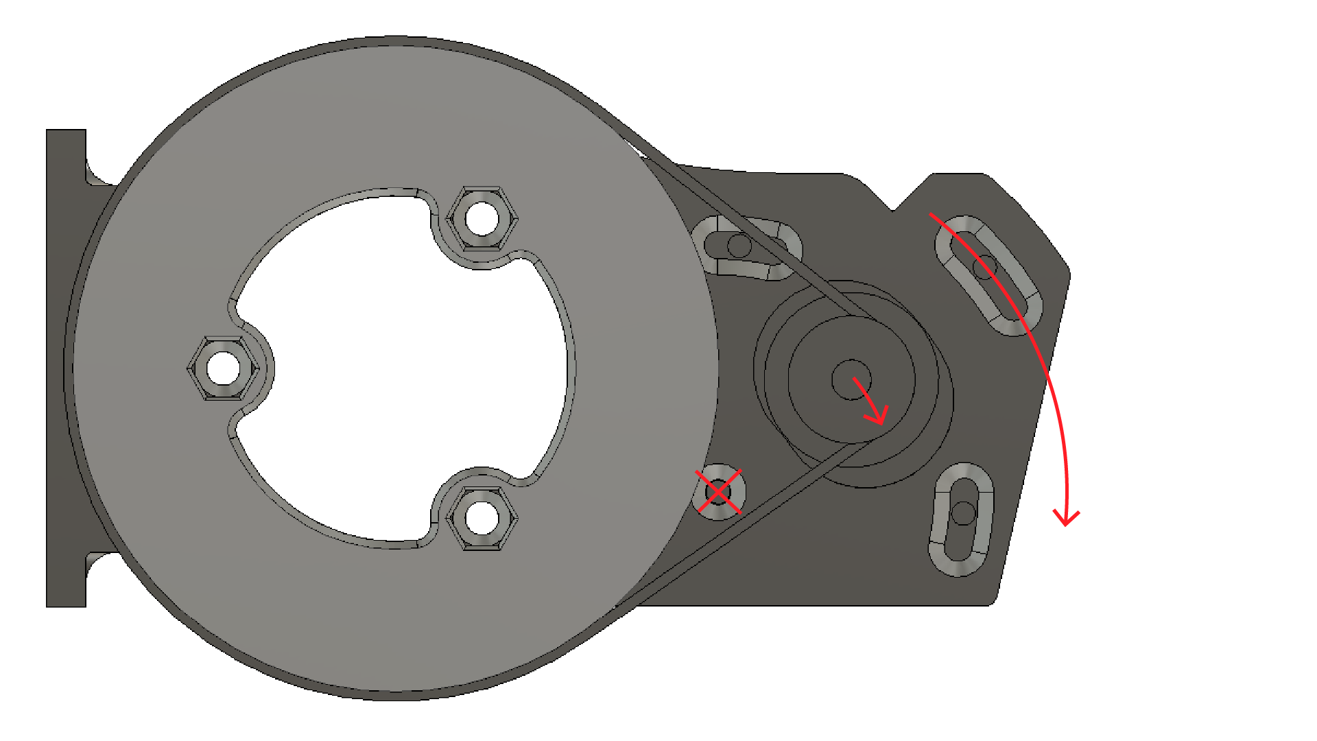
Trick #2: Motor-Rotating Tension
This is a trick that I pulled from the Prusa I3 machine, which uses the same method for x-belt tensioning. We simply fix one of the motor mount holes, and sweep the others through slotted arcs, then we can rotate the whole motor around its pivot in order to tension the belt.
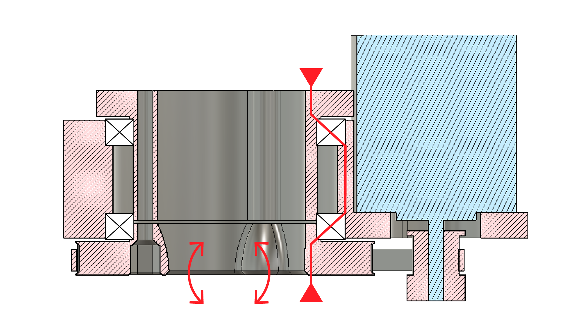
Trick #3: Moment-Loaded Bearing Preload
Finally, we often want these rotary devices to resist motion in off-axis loads, i.e. “momentary” or “bending” loads which bend in axis that are… not the rotational axis.
Setting our bearings up as shown - so that they are pinched together along the inside race but held in the stationary body along their outside races means that our pre-loading load path goes through the bearing balls along the same path no matter what loads are applied to the end of the rotary device. This helps a tonne in positioning (eliminating backlash that might arise as bearing balls walk around).
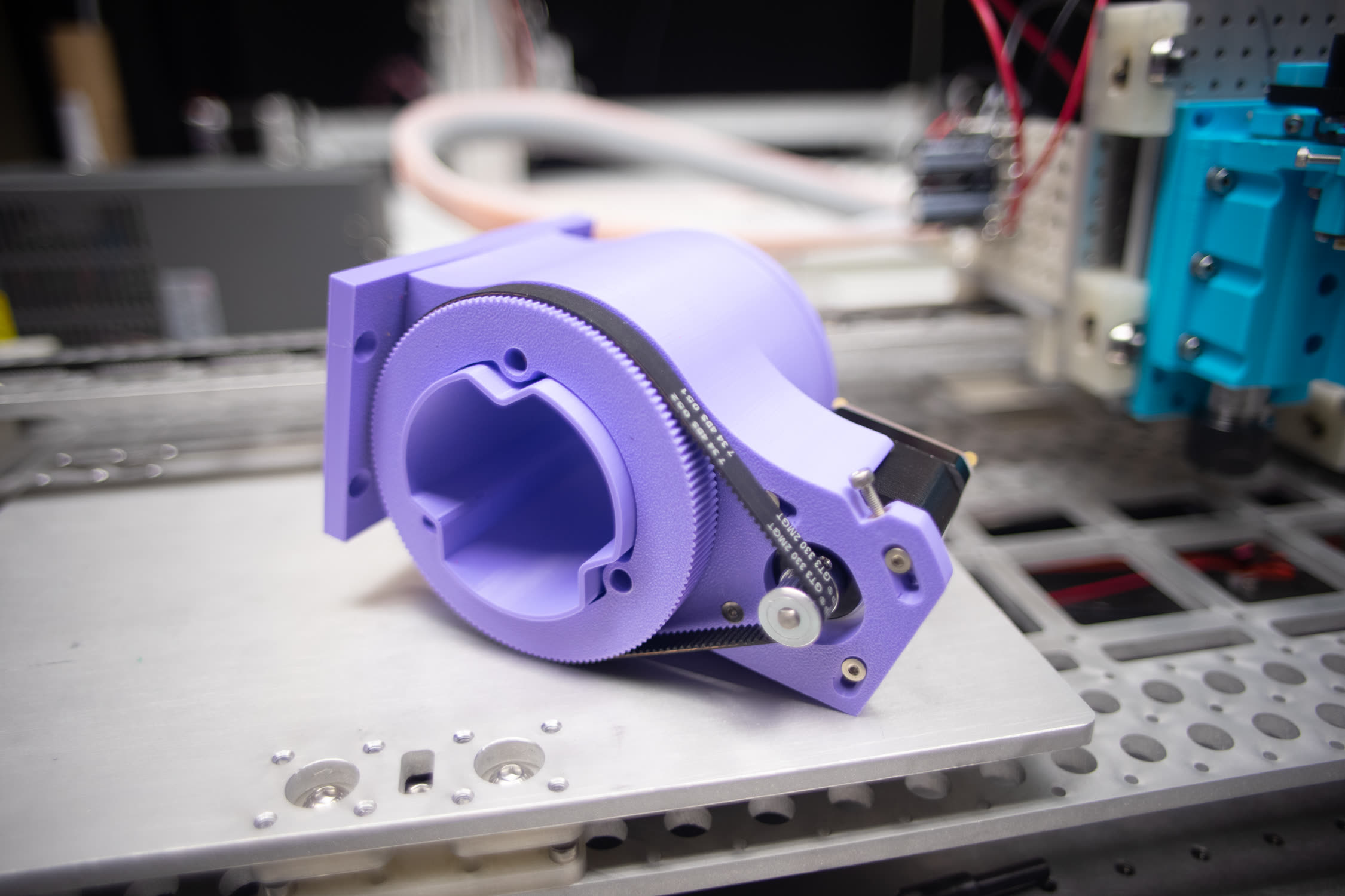
Rotary in Action
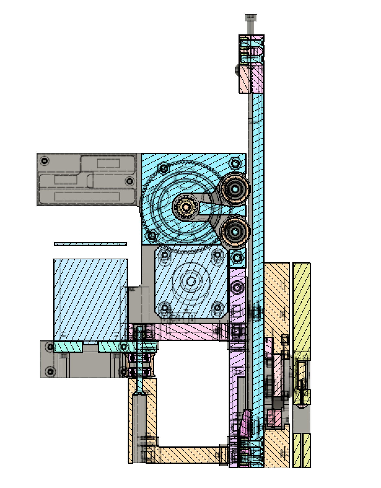
Finally, here’s the thing in action, in an origami creasing machine. The rotary end-effector here uses this design pattern, as does the z-drive, which uses it as a single-stage belt reduction, before passing on to a linear belt:
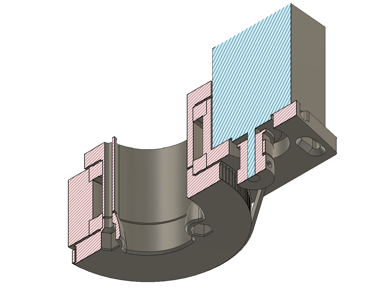
I’ve included a detail of that z-axis here, this is from the Clank! project - you can see in this section the rotary reduction in “behind” the section (ghosted lines), and the linear belt clamps on the top and bottom of the Z axis, and two idlers which wrap the linear belt around the pinion.
« Clay Printing (round 1) at Haystack
Ceramics Output »