Laid Up Gantries & Capstans
There’s a gitlab repository with CAD and more detailed design logs here.
This log is output from a few months (2020-01 -> 2020-03) long experiment in two DOFs: one, to build high performance machine structures using ‘laid up’ (epoxied on reference surfaces) composite stock, and two, to build high performance machine transmissions using the capstan principle.
TL:DR / Capstan Conclusion
Capstan drives are close and promising but in the end are too sensitive to quality implementations for me to continue their use in ‘rapid’ machine building. As Neil would say, ‘too sensitive to parameter tuning’. I hold out that, done well, capstans could help to build really killer hardware.
TL:DR / LUG Conclusion
Laid Up Gantries will be my favourite machine building method going forward, so this is a win. I expect this will apply across materials: here I’ve used Phenolic composite sheets which are cheap and stiff (relative plastics: about 12GPa modulus) and machine beautifully on a shopbot, or, our Zund. The same technique could be used with steels, aluminum (although bearing surface is TBD) as well as with Acrylic sheet cut on a laser, and set up with acrylic cement.
Output
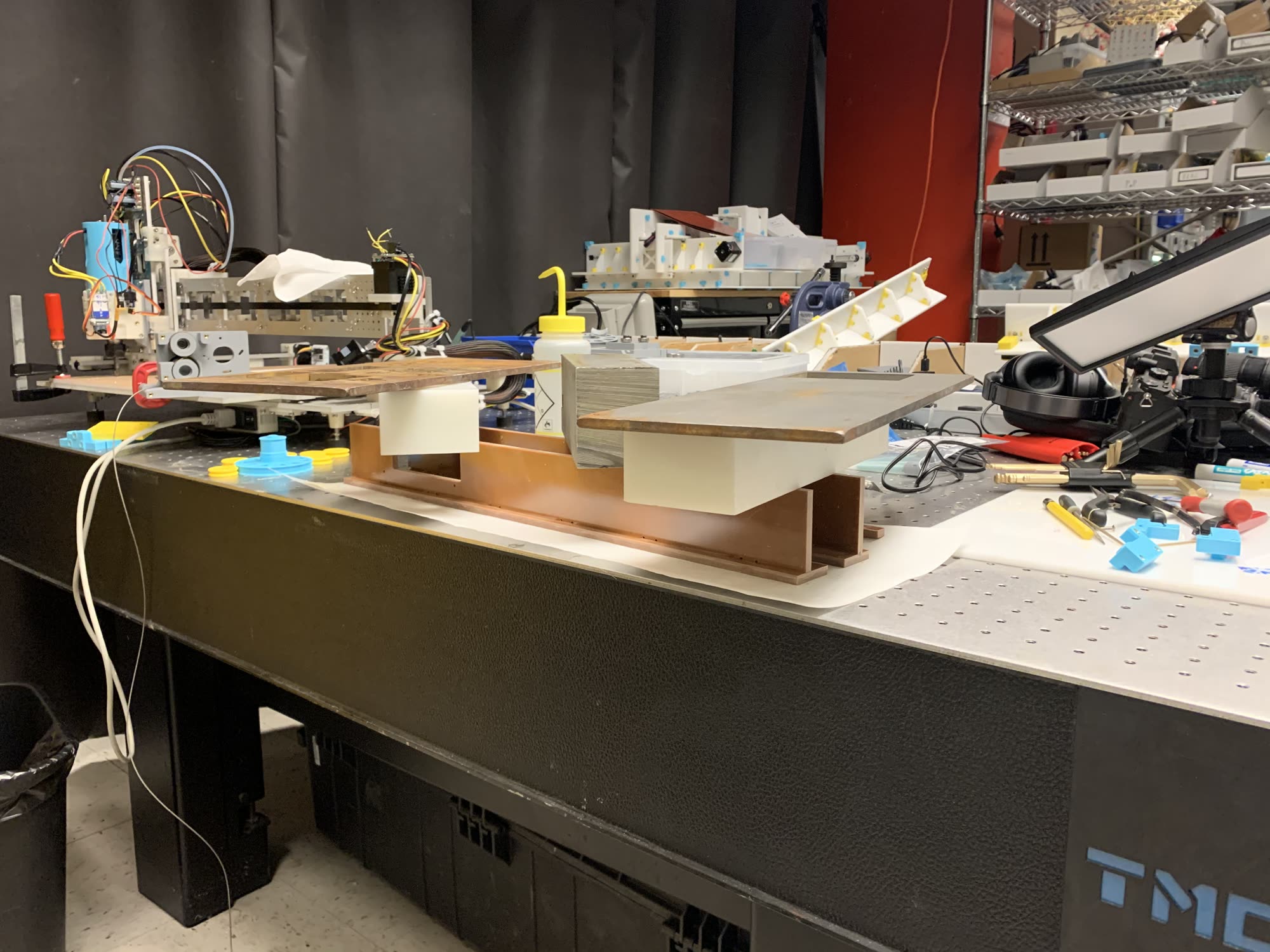
I built a few axis combining both of these techniques, and made one attempt at integrating them into a machine, the lc-smf.
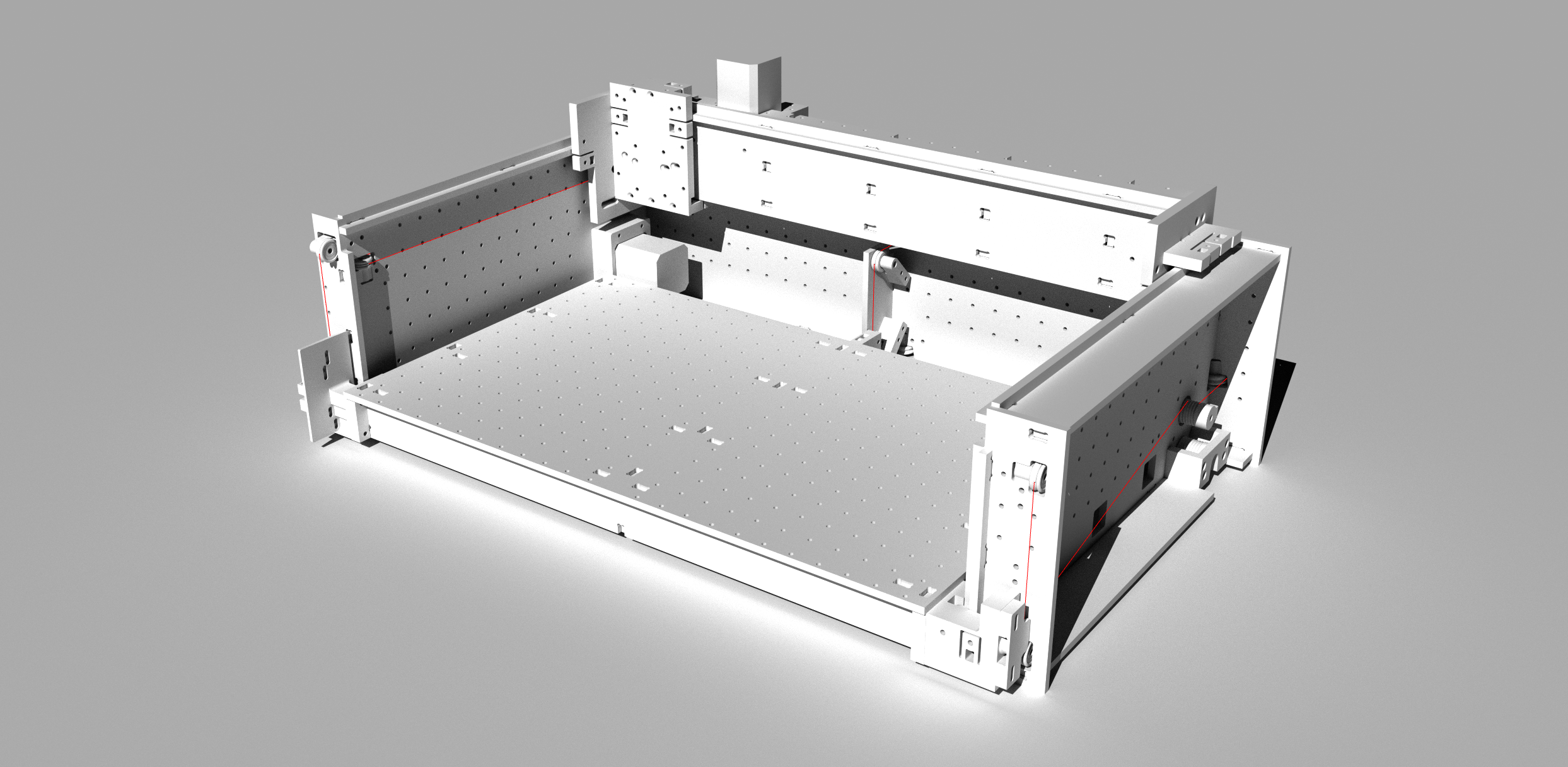
1: LUGs: Laid Up Gantries
To build rad machines w/ less-rad machines, we need to base the straightness of our structures on some quality reference. I.E. if a shopbot is straight to ~ 0.01” over 12”, this is the best we could ever hope to build into a new machine. However! If we reference a structure that is straight to 0.001” over 12” during lay-up, our machine components will come out with a similar straightness.
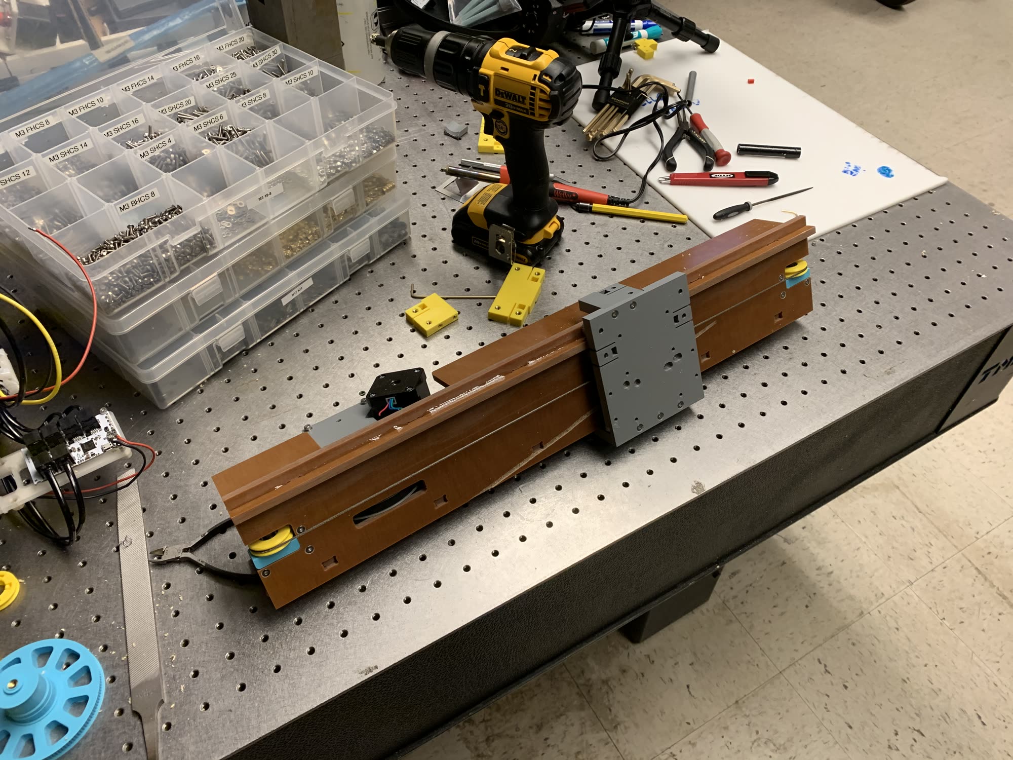
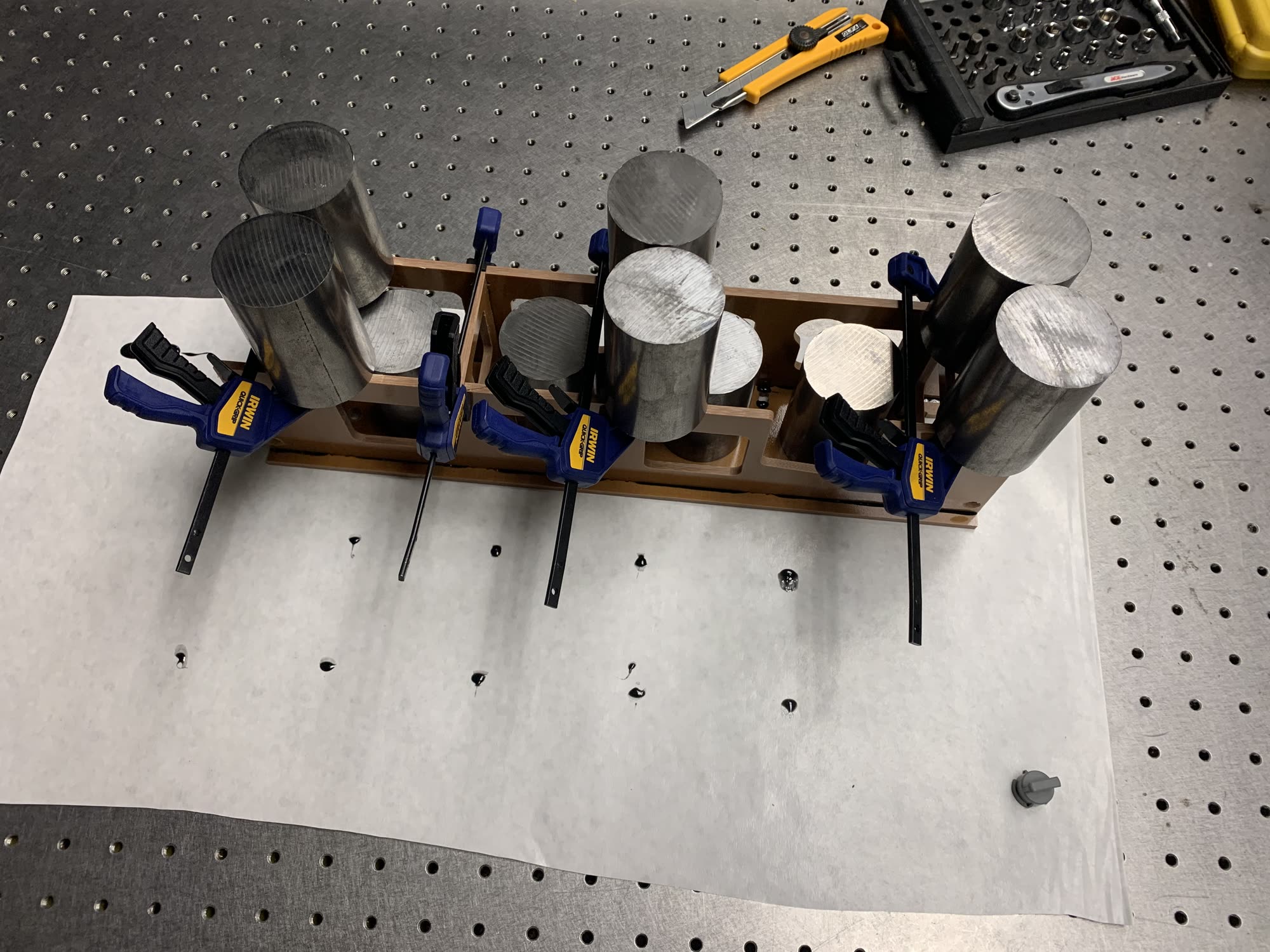
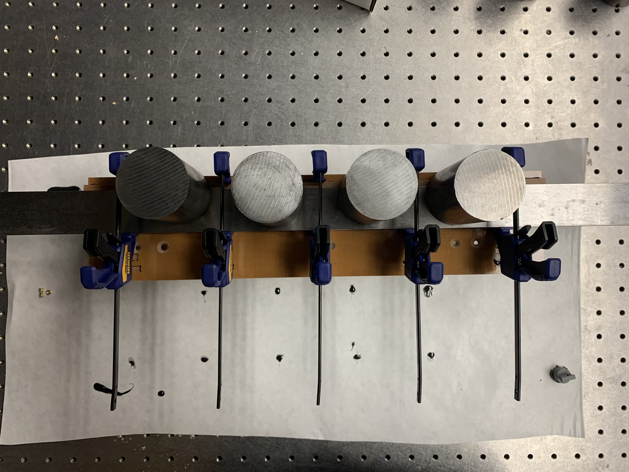
To do this, I steal accuracy from the optical tables in our dungeon basement at the CBA, laying up each axis with a reference:
The ‘rails’ protruding on the beam constrain one DOF … this little tag constrains the other side, so I lay it up with a reference straight. Here, that’s just a run of the mill centerless ground rod, but these types of reference edges are also available.
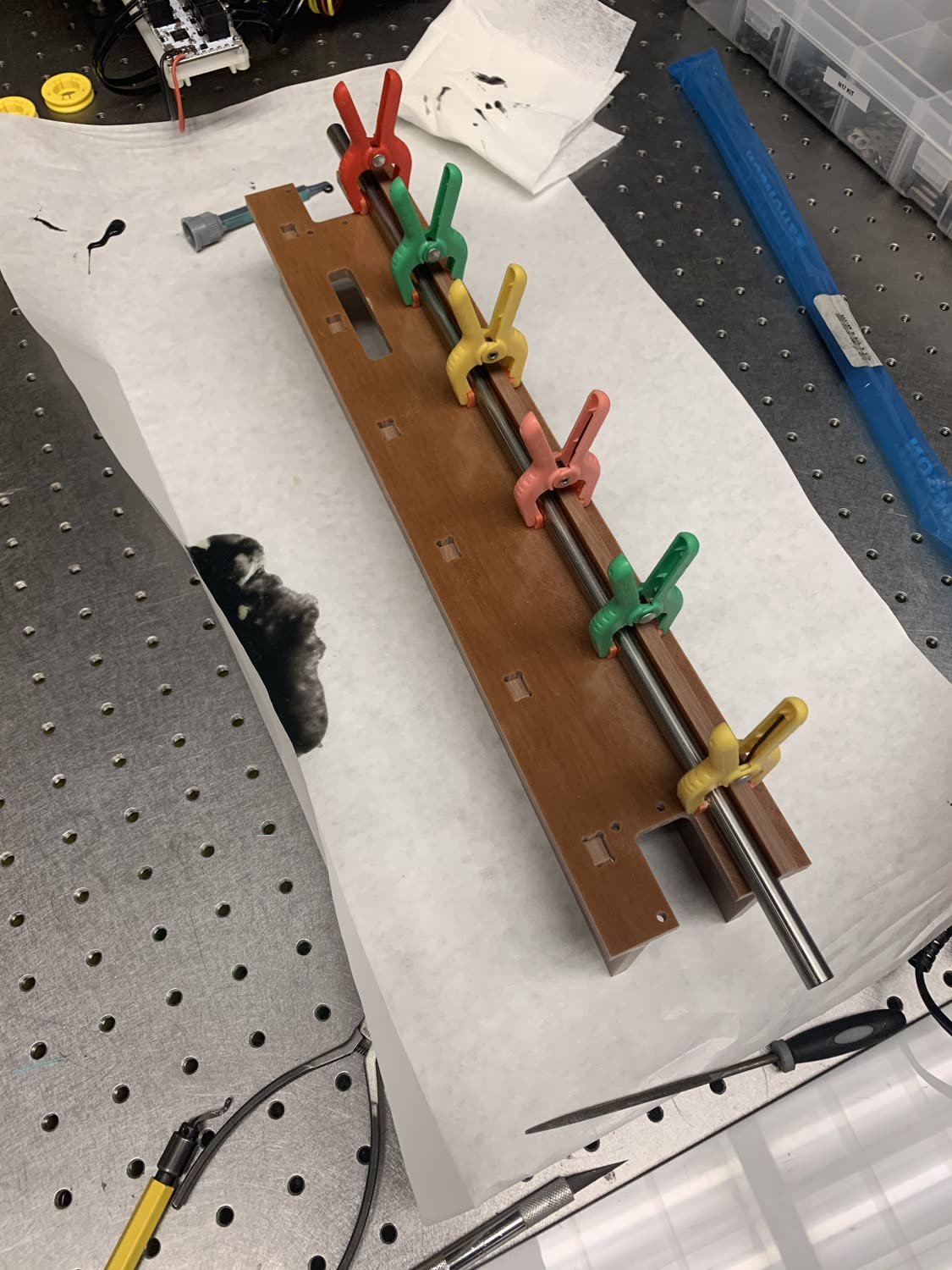
I later improved this by getting a straight edge ($75) from McMaster, and some weights.
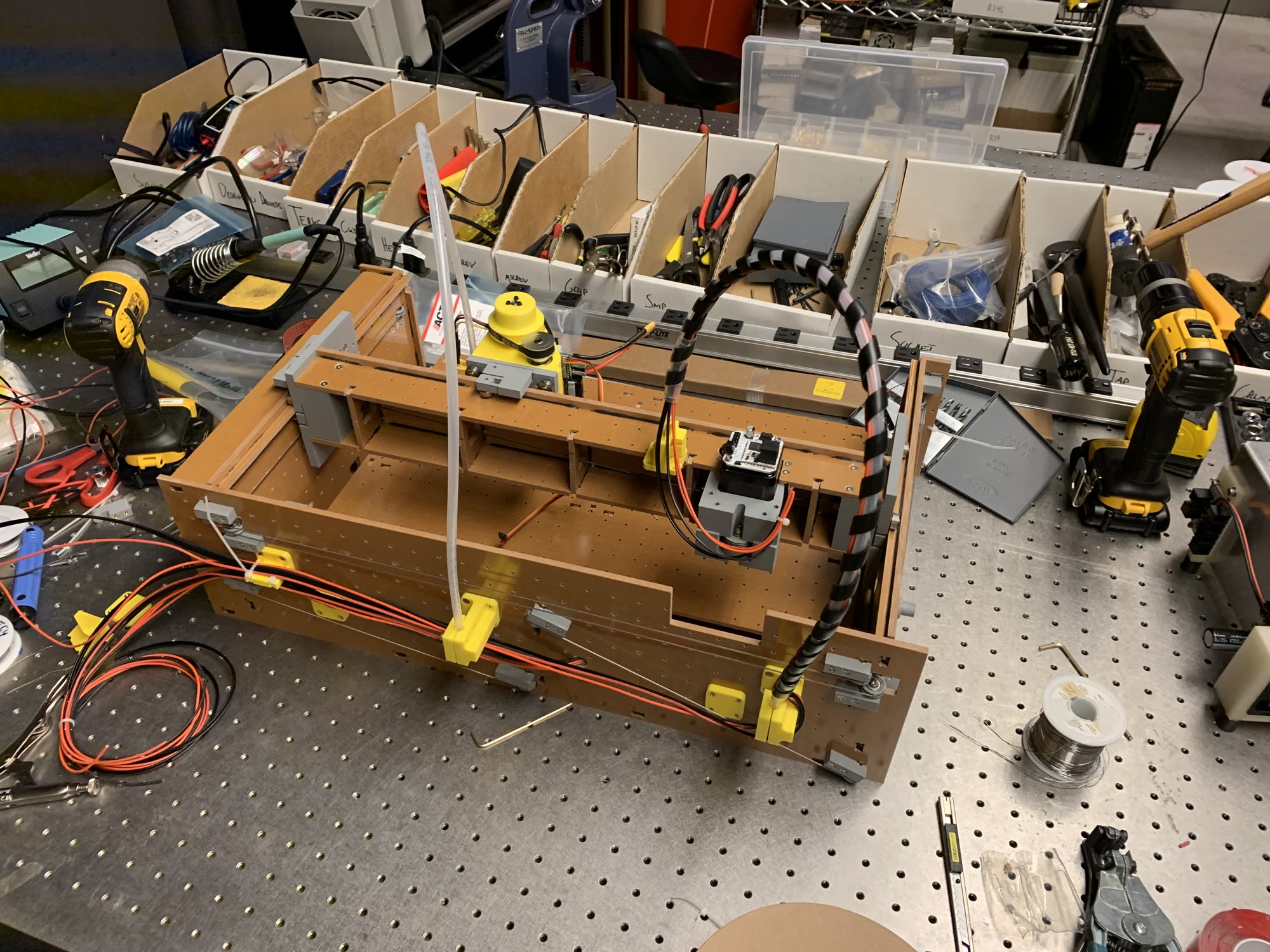
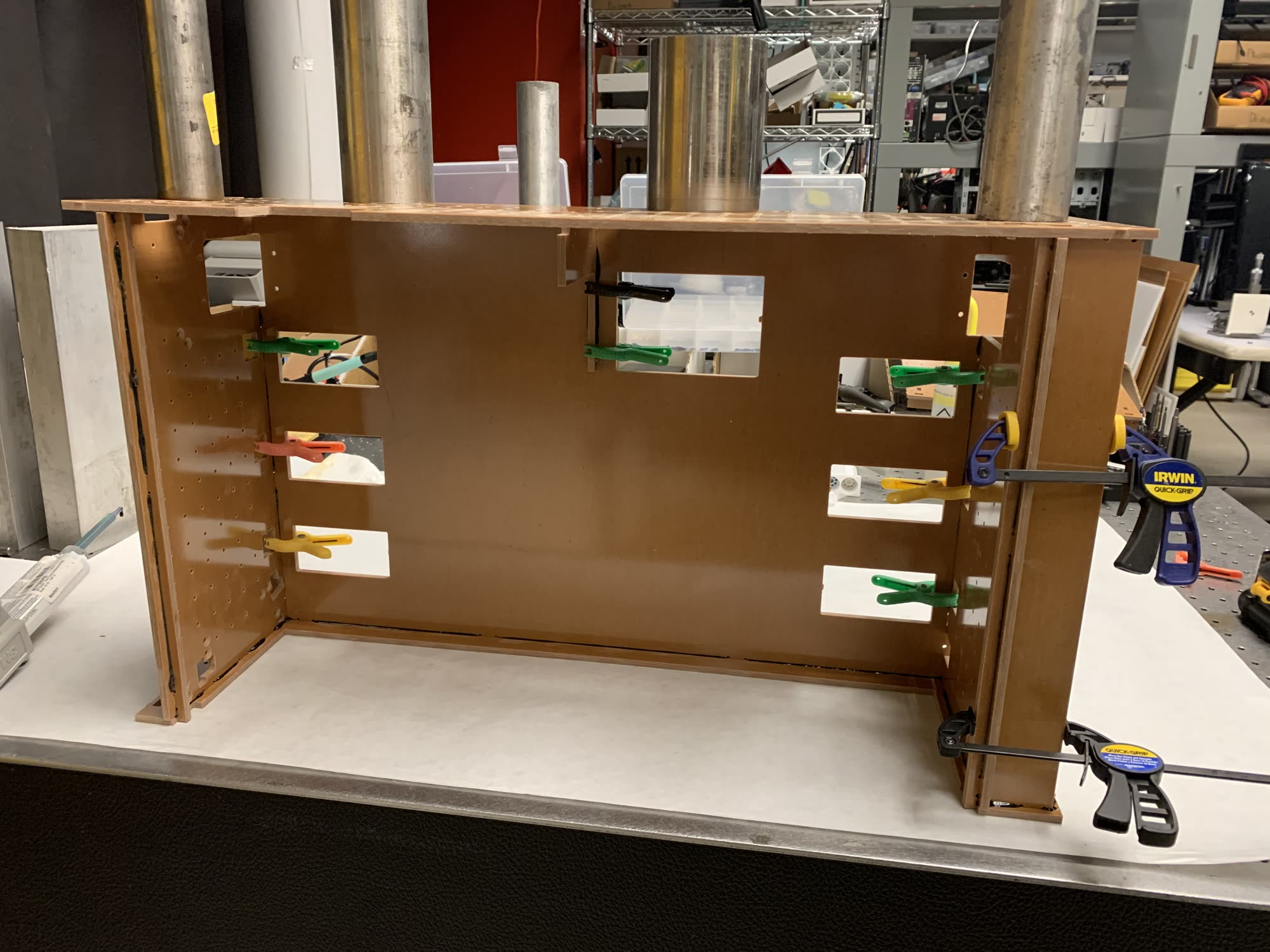
As rail structures and chassis are integrated, it meant laying up boxes like this:
2: Capstan Drives
Everyone loves a nice cable transmission. Steel Rope is stiff, strong, available around the world, and can be routed easily around a machine. Idlers are simple, and driving elements can be featureless (i.e. we don’t need to machine teeth: we just need a lathe (or a printer, depending on your quality of shop)). This is all a result of the most-excellent capstan equation, where the loads we can carry on these pulleys goes in the exponent to the number of times we have wrapped the cable around our capstan.
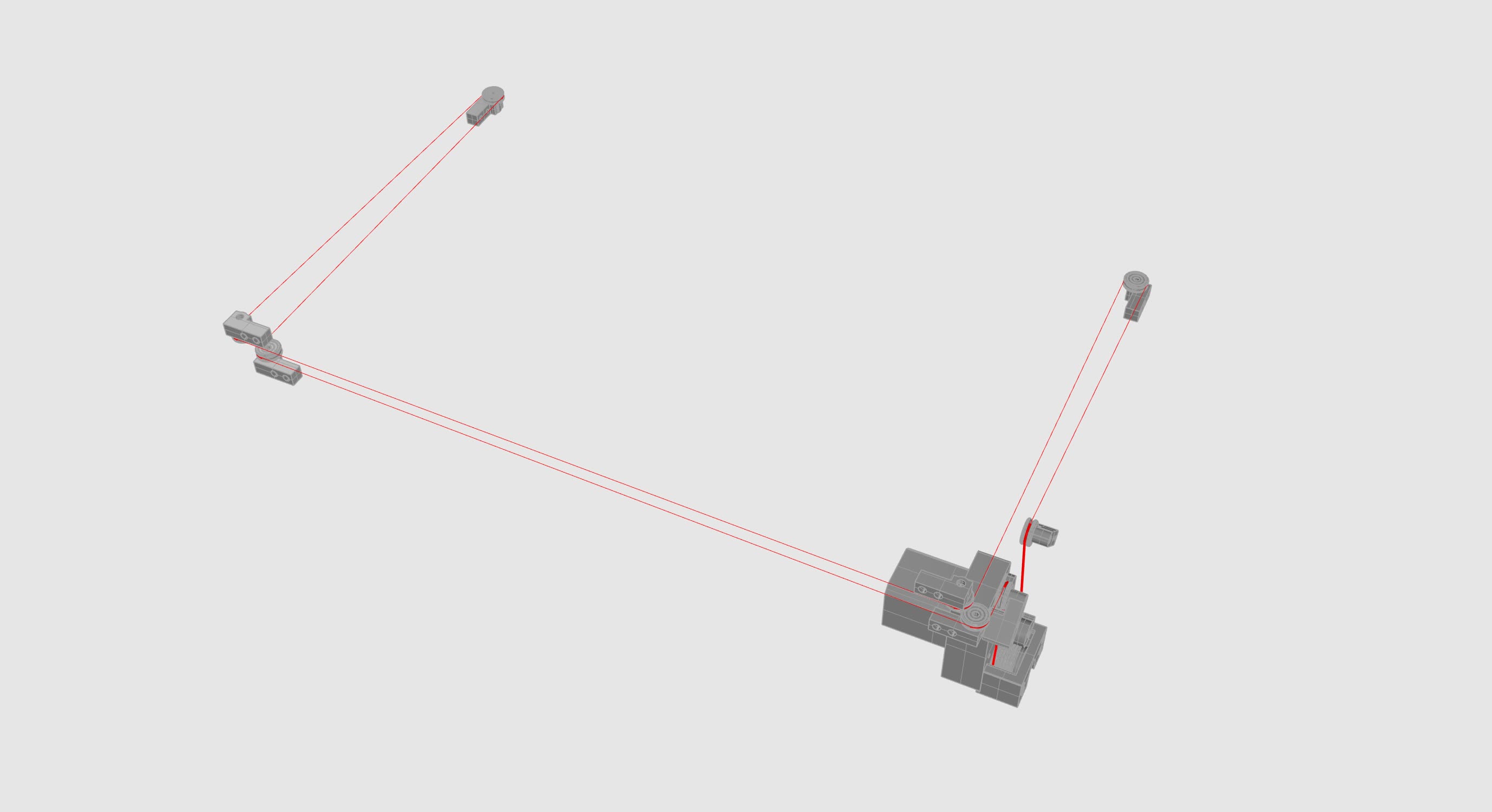
One trouble with capstans is that we typically need lots of capstan length… as in this image:
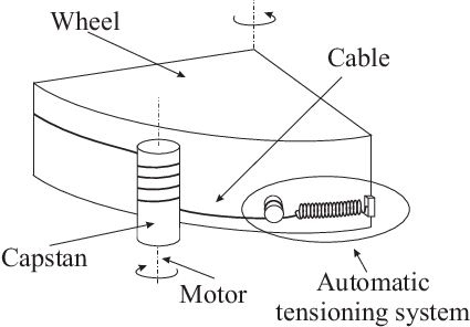
The capstan needs to be ‘tall’ enough to cover the entire length of rotation. That helix is baked in, we can’t shear the cable along the length of the capstan during rotation. This makes it difficult to implement a capstan drive in the way we normally handle belt-and-pulley transmissions.
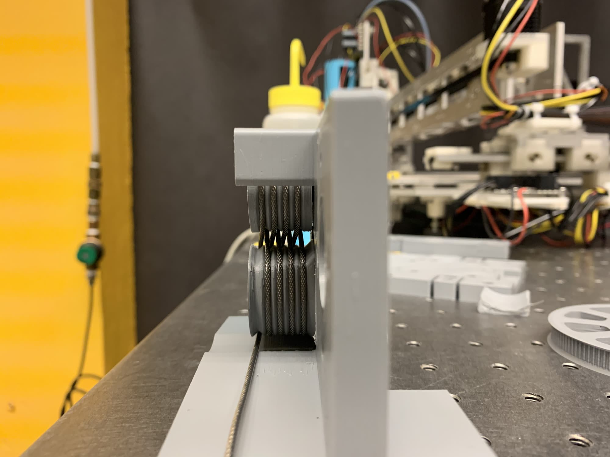
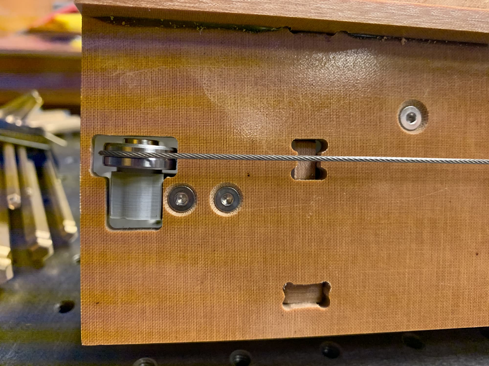
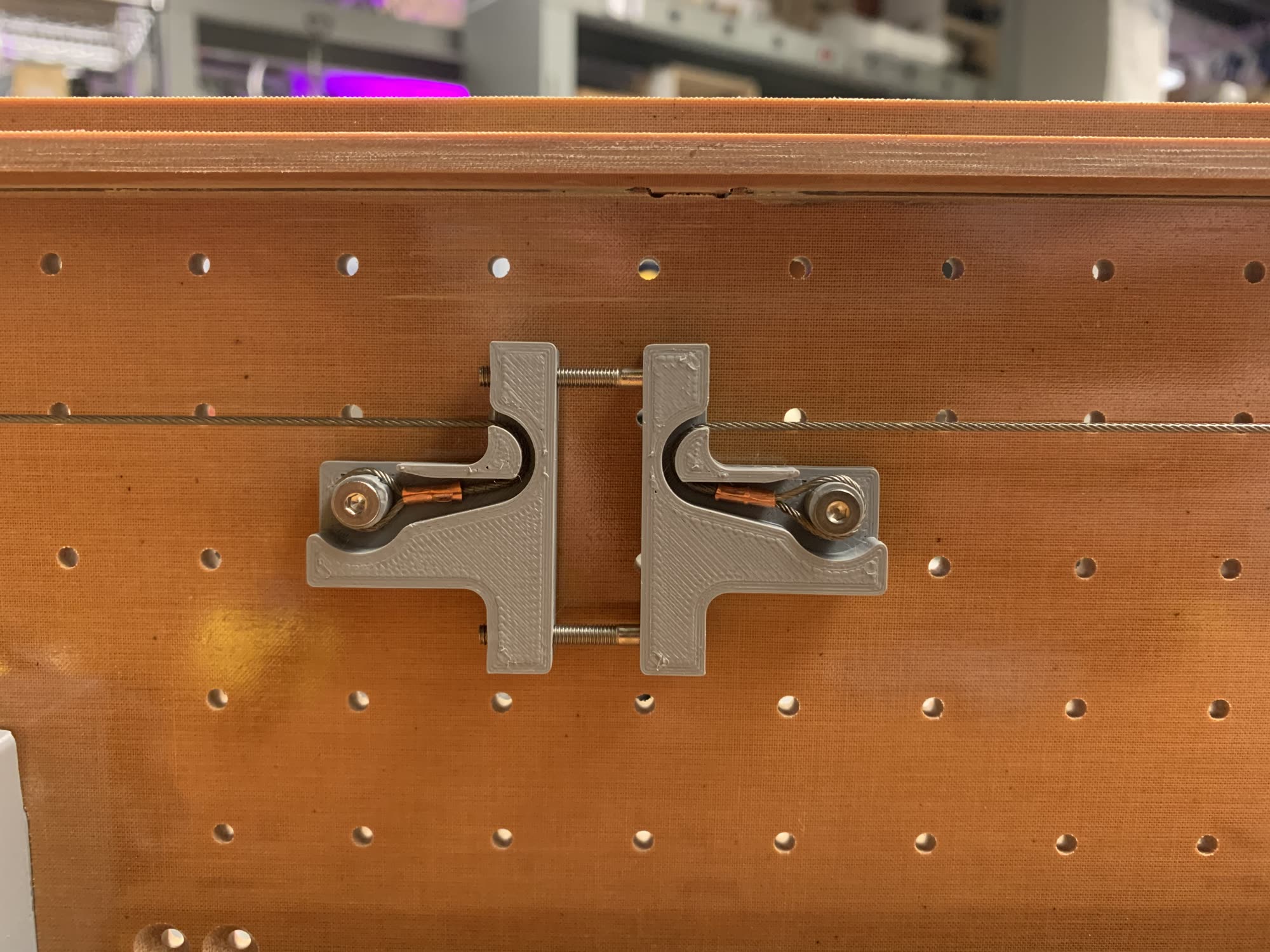
Many capstans feature helical grooves to keep the cable in order in this helix. This brings some determinism to where-all the cable will roll on to the capstan (along its length). To do this without a helix, so that the capstan always rolls on in the same location, I use this double idler system, with grooves on both:
For a better view of this, I have a video:
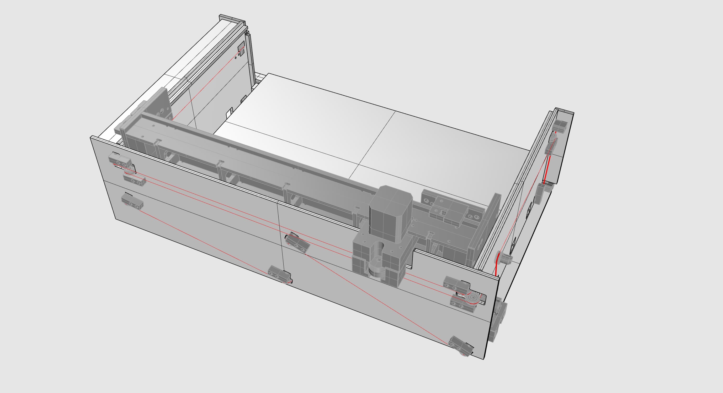
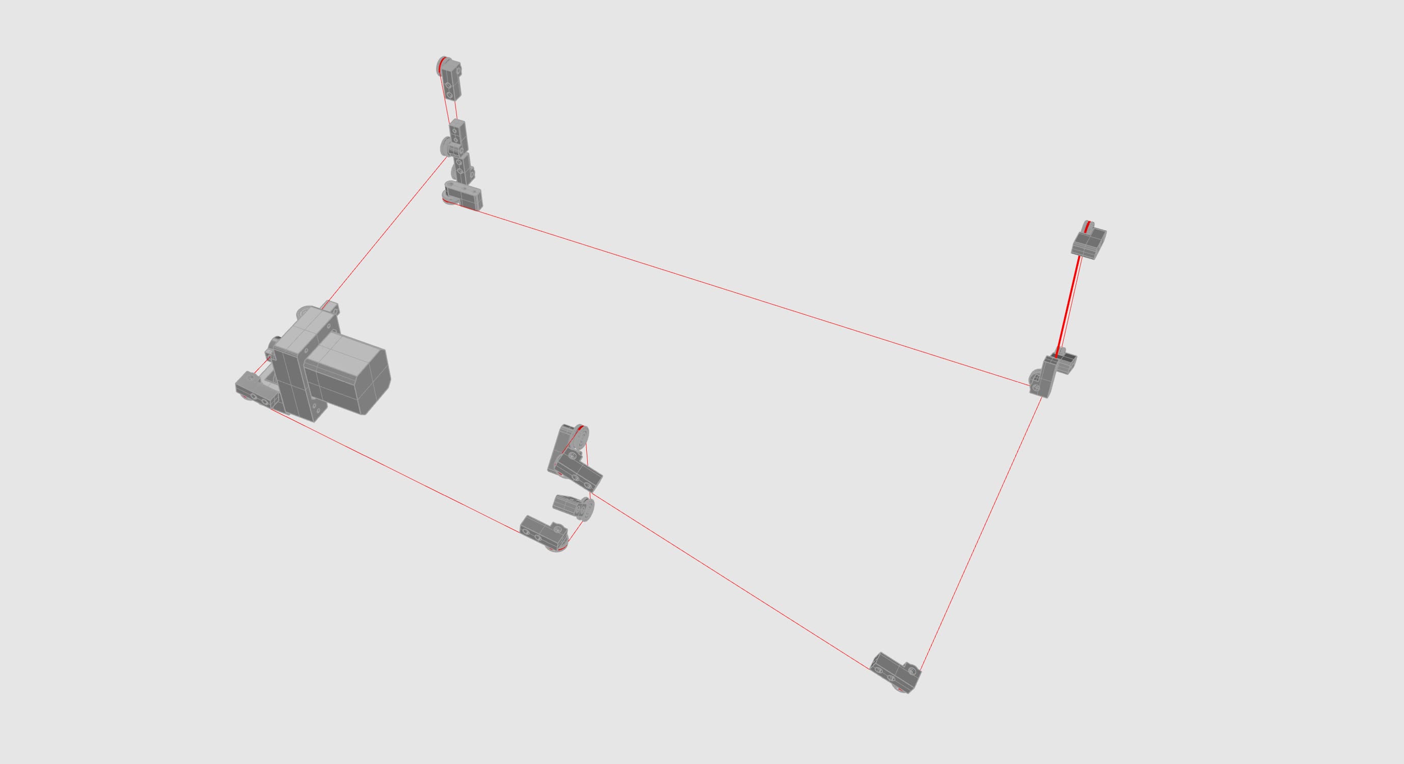
This is just-neat for one axis, but is really cool when we want to whip the drive element around a machine chassis, a-la the LC-SMF machine. I can ground motors in little ‘drive units’ and then, weaving the rope around the double-grooved setup above, am free to route the wire rope around the machine.
Here’s the bed moving w/ this scheme:
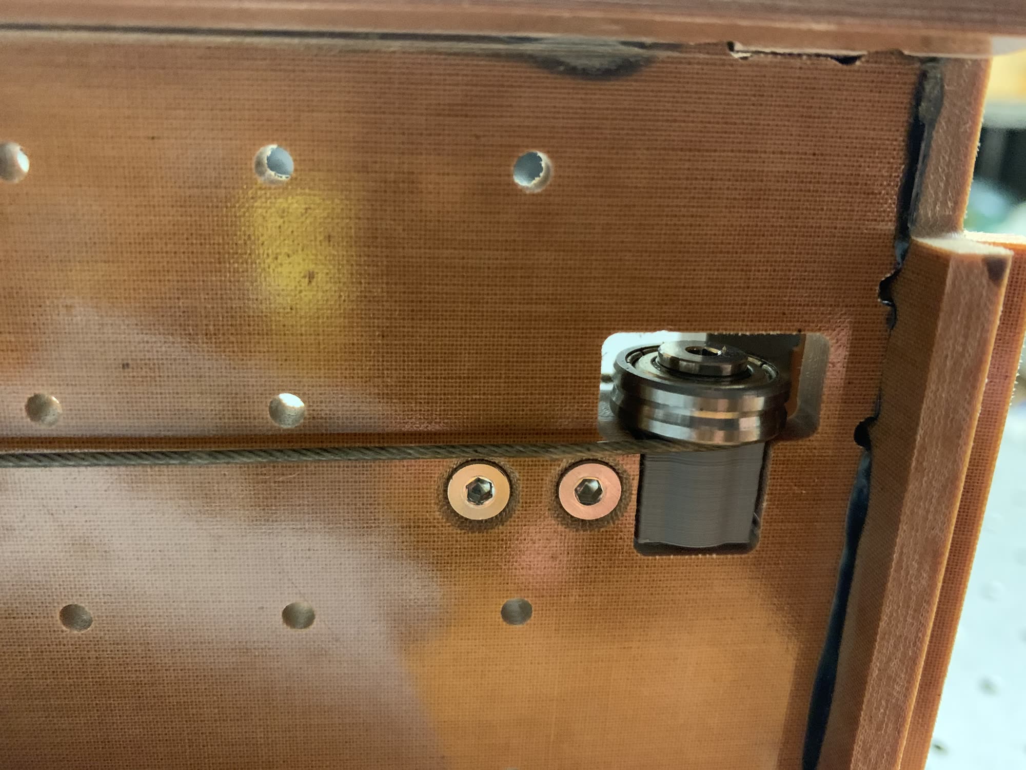
One truth that eventually emerged here is that every element in this chain needs to be stiff for the rope transmission to be stiff: i.e. idlers:
I also noticed a strong desire for concentricity on idlers. Any printed parts were just not good enough to really bring a satisfying amount of tension into the system: small deviations on concentricity would cause tension to increase in spots and decrease in others. The bearing above is a special purchase part with a small groove machined in place.
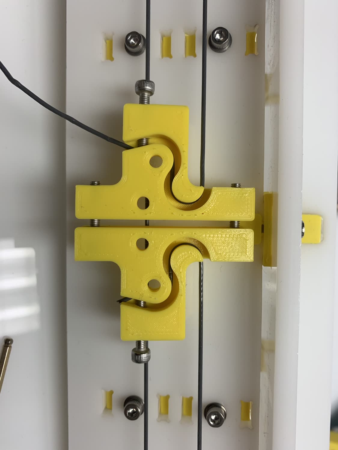
The system overall was also difficult to route: often, and especially if the machine was ever crashed, wire rope would jump off of idlers:
These were a pain. That said, enough patience and it was possible to get a great deal of tension into the thing:
And a test crash:
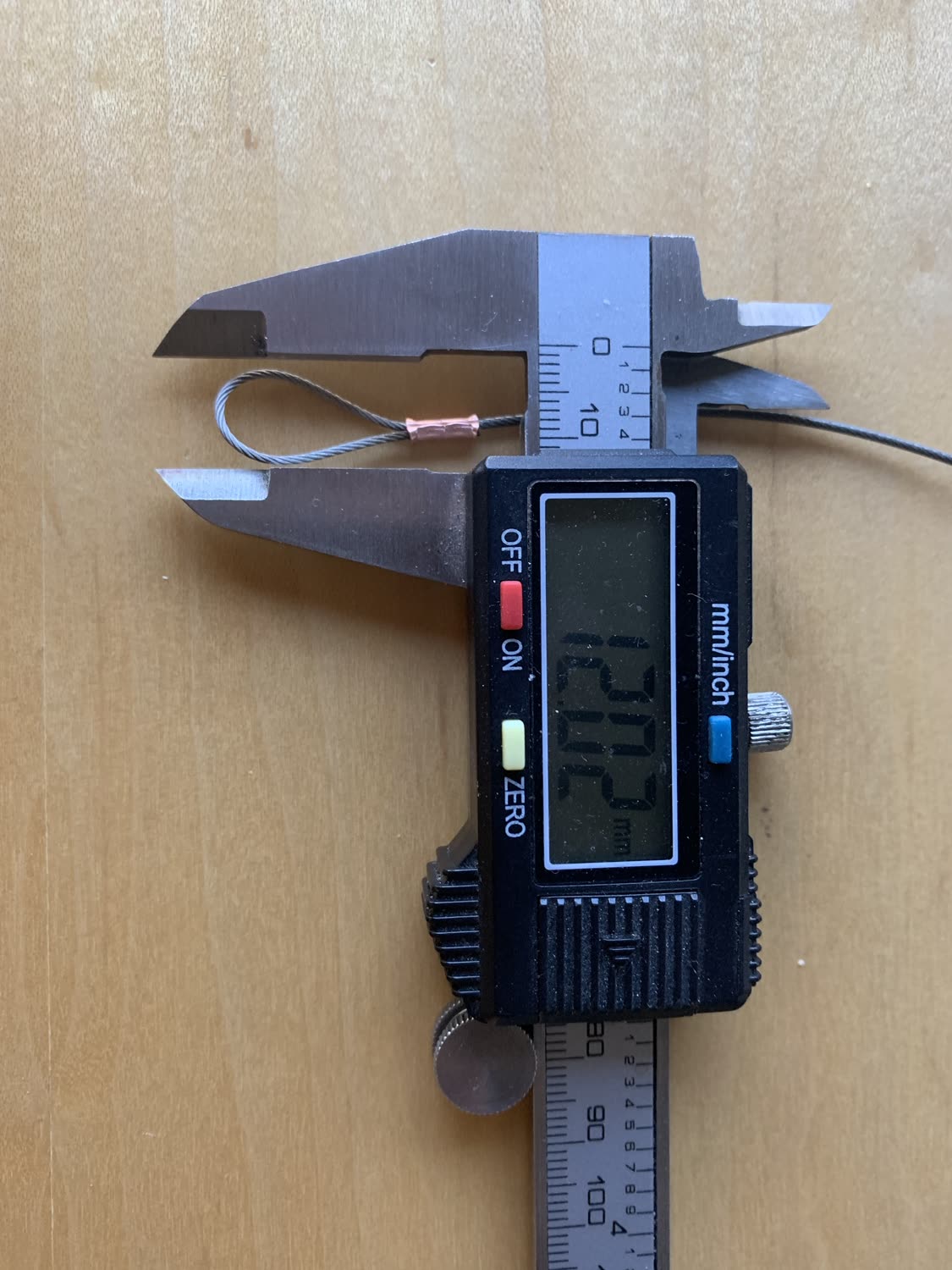
Mostly I learned that terminating these properly is really important. At first, I tried this halfway solution:
But I eventually found proper wire crimps were the way to go:
These held the right amount of tension, but with long runs (especially the serpentine paths above), it was difficult to terminate at the right spot. Again, done well, this could be great, but my patience ran dry. May capstans live to see another day…
Capstan Parts
These were my picks in the end, for small-sized transmissions such as this.
| Que? | McMaster PN | etc |
|---|---|---|
| Wire Rope | 8930T54 | Choice! |
| Loop Compression | 3897T31 | (100% rope capacity) |
| Stop Compression | 3926T42 | (40% rope capacity) |
« Kerala Super Fab Lab Install
Reflections on Clank-LZ from HTMAA »