Reflections on Clank-LZ from HTMAA
this is a mirror of notes in the gitlab repo, where CAD files are also available
I’m closing out on Clank-LZ today, moving on to build out the toolchanger-complete Clank! platform so I thought I would do some summary notes & organize this repo for future observers of the project… / for my own peace-of-mind.
What We Did
In around June 2020, I had been developing Clank as a machine system targetting ‘small’ CNC: 3D Printing, PCB Milling, Pick-and-Place, Automated Pipetting, etc. The broad plan was to have a friendly (easily fabricated, straightforward) set of machine designs (axis, tools, and a tool changer) to handle almost any CNC task outside of heavy duty / high load applications - a kind of generalist.
Given the state of the coronavirus pandemic, we realized that we would be teaching how to make almost anything in a largely remote fashion. While I originally hoped to complete a ‘multi-process’ machine that students could use for CNC Milling, 3D Printing, as well as PCB Milling, we later decided to downgrade the scope and develop a standalone PCB Mill.
So, this was:
- the design of a machine kit to be produced in-house on a printer farm
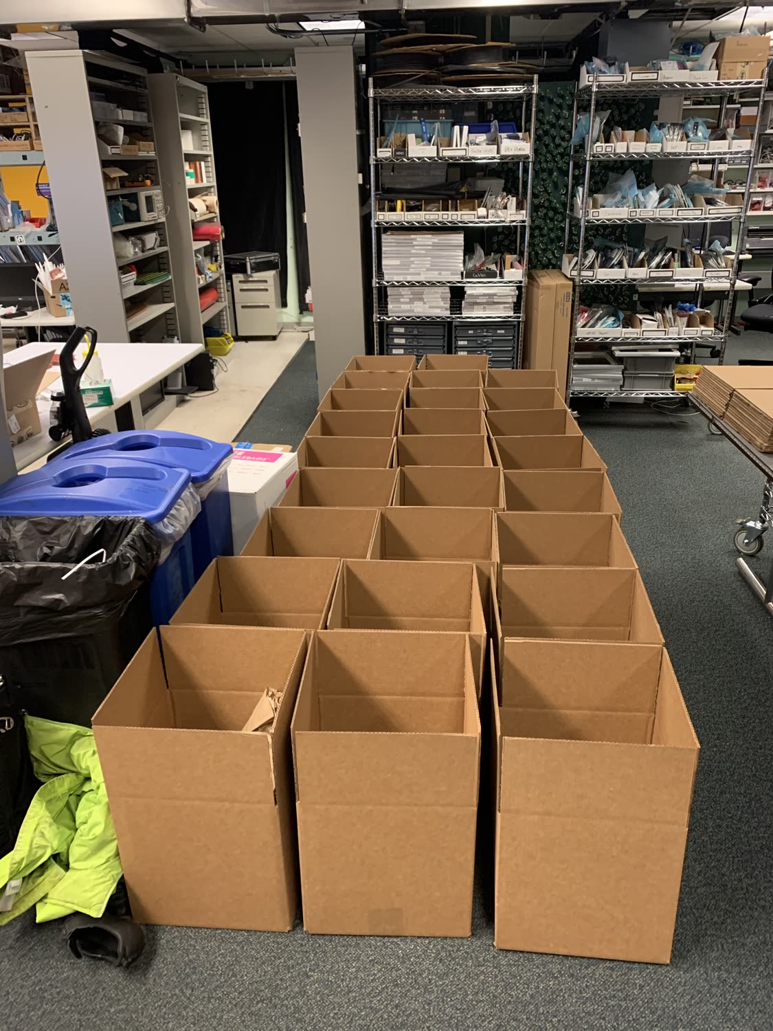
- the assembly of 30 kits,
- the development and assembly of a machine controller for the same,
- documentation for students: how to assemble the kit, how to run the controller
Given our small class size, this turned out to be a feasible exercise and in the end things ‘worked’ - students were all able to assemble their kits and used them to complete PCB fabrication assignments.
However, it is hard to say if this approach (designing our own machine, our own controller) was indeed any better than simply purchasing off the shelf machines and controllers. Our final machine BOM totalled around $400 for hardware and an additional $160 for controllers. In some regards, we were using this as an experiment to test our internally developed machine systems - so the value makes sense on our end, but doesn’t necessarily make it a repeatable exercise.
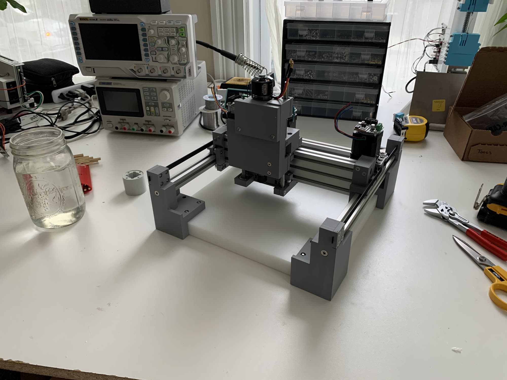
About the Machine
The primary interest was in building a machine that was easy to assemble and understand for students - that was largely a design exercise, and difficult to evaluate. Given that we didn’t appropriately query students on their experience, it’s hard to say whether this was successful. Some did use Clank design elements in their final project, and some were also able to use parts of it’s control system in their project (i.e. hijacking the power supply to drive their creation). This is the aspiration: that what we provide students is extensible so if i.e. they would like to develop a new end-effector for a machine, or some project driven with stepper motors, they can take design principles and entire parts of the machine kit in order to do so.
The cost of hardware - $400 - is largley eaten up in the spindle assembly, totalling $150, and a surprising amount of PLA, $72 worth per machine. Cables, plugs, and the PSU itself were another $90. Each of these aspects could be cost reduced.
The cost of 3DP fabrication was low initially but tending a print farm is not a small job, I found myself in the lab every day (sometimes twice) for about three weeks. A big take-away here was to organize build plates into long (~16 hour) and short (~ 6-8 hour) shifts - this minimized massive jobs of ~24 hours (liable to fail) but allowed me to be in lab twice a day (in the mornings, and then afternoons) to keep printers running around the clock. We used Prusa MK3 printers and I was careful to make sure bed adhesion was maximal whenever changing a print - cleaning and prepping (with glue stick) each job. I later discovered some specialized adhesion agents that work even better, and would use them if I were to do this a second time.
I think that the value for students of having on TA staff the individual who designed the machine is worth noting. This is my own experience: when I was younger, I never imagined I would become any kind of programmer. I understood it to be a thing that humans did, but it was only until I met some talented programmers myself that I realized this was indeed something that mortals did, and became confident enough to see myself doing it - that’s when I started learning. I would like to hope that, because students could meet and interact with me (although virtually) and also build my machine hands-on, they saw that this kind of project is something which can be undertaken without a huge amount of learning beforehand.
Machine Documentation
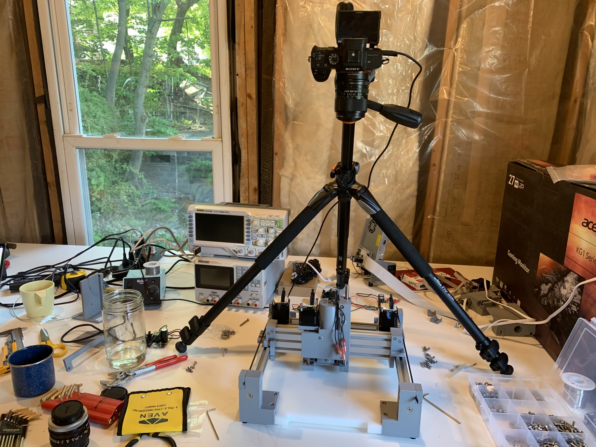
While written documentation is great, I spent just two days filming a series of build videos for Clank - students reported that these were invaluable. I did this with an overhead camera, and simply built the machine start to finish on the desk. When I felt like it, I would make comments on the machine’s design, or other mechanical subtleties: the use of a flathead screw vs. a socket head screw, bearing preload, kinematics, belt stiffness, etc.
These videos are available in the repo’s build log.
We also provided relatively complete (i.e. having machine screws, bearings, etc in-model) CAD files in various formats to students, for their reference. Since they were simultaneously learning the same CAD platform that the machine was developed in, this was a great way to document as well as increase comfort in the program; a bit like seeing the source code of a piece of software while learning it’s API.
Hardware, Next Time
We still aren’t sure if building our own machines is worthwhile, and recently found a $150 PCB Mill available off the shelf that suggests it is at least not worth the money. However, the value of building a tool specifically for the task of teaching PCB fabrication could be invaluable in the future. We didn’t have enough time to properly develop Clank as a specific tool (recall that it started as a ‘generalist’). On a next run, I would do a few things differently:
- simplify the XY stage for cost and complexity, given smaller load constraints. smaller motors, etc, maybe a corexy implementation
- greatly simplify the spindle: this is something of a design problem, but I’m working on a ‘roller’ spindle where the endmill shaft is driven directly, resting on a series of rollers instead of within a collet… track this project to see this design in the future
- the Z axis can simplify into a flexural design, greatly reducing cost and complexity
- Clank uses a lot of nylock hex hardware, instead, plastic thread-forming screws can be made to work: this would reduce CAD complexity as well as assembly time and BOM cost
- some students missed subtleties like belt tensioning, spindle direction, and some screws were left loose. these should be addressed in CAD where possible and in documentation
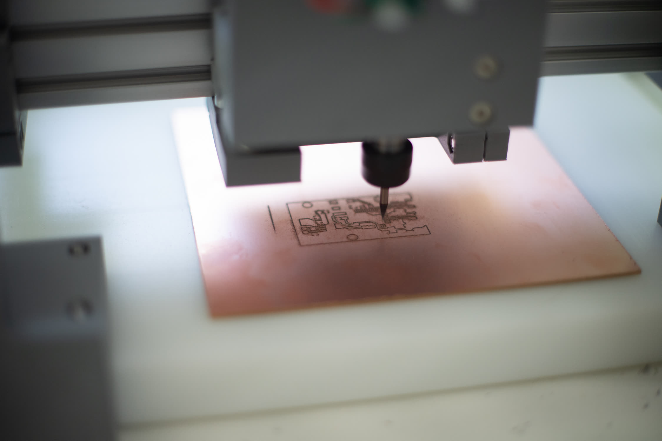
- pcb milling features like auto-z-homing and surface levelling would greatly expedite student success,
About the Controller
What’s true in hardware was true in software as well: we used a modular system that was in development for general purpose machines where, were this to be a focused exercise, a single monolithic controller would have been better suited. The modular system meant that each motor recieved its own driver node ($30 each) as well as a ‘head’ ($40) at the PSU and an ESC controller for the spindle. This modularity was superfluous for the purposes. It did, however, further my own development of the system for research purposes.
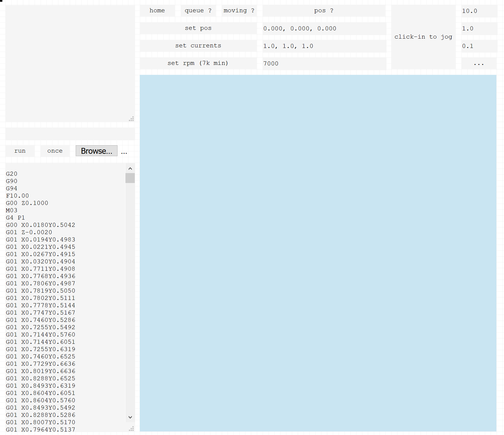
The controller served a browser interface, but students still had to install a local instance of node.js to run it. Luckily, this didn’t pose many problems, and node as well as the browser’s inherent cross-platform-ness meant that everyone was able to get off the ground without any trouble (I actually didn’t test on any platforms other than my own - so maybe just got lucky).
Controller Documentation
This was, admittedly, more sparse than machine documentation. I filmed a few cursory videos on how to boot and run the controller (available in the controller repo), and some text documentation, but little else. This did the job - students were largely able to get up and running - but a few had some struggle installing node.js, understanding the workflow, etc.
The Controller, Next Time
Since then, we’ve noticed that the Raspberry Pi 4 would serve well to make this simpler: we could run a webserver & local host on the Pi, as well as (since the Pi has what looks like good UART support) embedded output to motor drivers etc. The rest of the controller (low level timing, sensor readings, motor control) could be relegated to one (not 5) circuits, purpose-built for a PCB mill. We would likely aim to keep a modular drop for the end-effector, but not modularize the entire motion system. The Pi 4 also does well as an entire desktop computer, meaning that students could potentially complete the entire course there: design, development, and fabrication.
The controller is likely the best place for us to add value to the educational experience of students: while COTS machines in the sub $200 range provide enough mechanical bits (less stock, endmills, and have questionalbe precision), the controllers they provide are lackluster. For PCB Milling, having a workflow that allows students to export design files into machine code smoothly remains cumbersome, and remained cumbersome with Clank: this is where we should focus efforts.
In Conclusion
The exercise was certainly worth our time as researchers, and I personally understand better the scope of projects I am able to complete, when focused. However, given more time, it would have been valuable for other educators had we focused on developing a platform more well tailored to education. As it stands, Clank represents a research direction that was put on pause in order to develop what looks like a kind of ‘product’ - vestigial aspects (overbuilt mechanism and controllers) that did not have enough work on their front-ends to serve novices.
So the lesson, as in most projects, is to try to do better in defining scope & expected outcome at the start, instead of rushing in to make some cool machines and spend a lot of time without any clear output.
That said, looks like the frontier of labs-building-machines-for-labs is approaching, and this was a worthwhile first-shot random-walk for an answer. Next time we’ll choose machine specialization over machine generalization when we want to build extremely low-cost, low-complexity tools for students.
Output
To see student work, you can browse the students’ documentation itself. There’s also a video of the final reviews where final thoughts / etc start around 2:14:54.
Issues
Just to keep track, here are some things that arose during the course of the term, in no particular order:
Controller Issues
- z motors overheating
- a configuration error on my part meant that default firmware for z-motor controllers drove 2x the necessary energy into the motors, causing them to get hot. a firmware fix (flashed by students, or TAs when they were unable to) fixed this
- stop-and-go buffers
- the browser interface dishes new moves to the controller on the JS event loop. when the browser is not in focus (another tab is open, for example) the event loop slows down. this would occasionally starve the buffer causing the machine to effectively pause, but bringing the tab back in focus ameliorated this.
- a workaround would involve some different buffering structure i.e. in the local node.js instance, which does not lose event loop timing performance ever
- bad ‘pause’ implementation
- again with the buffers, the embedded code buffered about 64 moves and the browser ‘pause’ only stopped new ones from being transmitted. so if a student ‘paused’ the machine, up to 64 (potentially long) moves had to clear from the low level buffer before the machine would actually stop
- motion control across scales is hard and requires some buffering. we are looking at cleaner motion control implementations that marry high & low level controller at higher fideltiy to do better
- bad usb cables
- a number of students had USB cables that included power lines, but no data lines (in the hardware… cable) these cables are commonly provided by vendors of (cheap) hardware, to charge via USB’s built-in 5v supply. they do not transmit data. these caused confusion, but swapping cables worked.
- provide a trusted cable, we forgot to
- lost bootloaders
- some (still mysterious) electrical events caused flash memory on micros to be erased, meaning bootloaders and code needed to be re-flashed, normally by a TA.
- enable students to flash firmware more-better
- develop an isolated PHY that prevents these kinds of events from knocking out entire systems (likely that GND planes tied together on RS485 link caused these issues).
- loose connectors
- the circuits use IDC connectors on 0.1” pitch headers, nice and simple. latching and non-latching connectors (plugs) exist for both: pick the latching type, non-latching would sometimes vibrate loose and cause havok.
Hardware Issues
- supply chain
- a late supply chain error meant that the spindle had to be re-designed. this was unfortunate, but surmountable. don’t use niche parts. in this case it was an
C8-ER11A-100L Collet Chuck Extension Rod‘collet holder’
- a late supply chain error meant that the spindle had to be re-designed. this was unfortunate, but surmountable. don’t use niche parts. in this case it was an
- loose belts
- a few students did not properly tension belts, resulting in sloppy traces. this could have been stressed more in documentation
- loose screws
- the same: these kinds of things are largely ‘by feel’ and some missed, could do better in documentation to emphasize
- set screws
- also loose here: most hardware on the machine are nylock inserts, meaning that things do not come loose over time. the set screws that hold pulleys onto motors are just small threaded aluminum set screws, and were likely to vibrate loose over time.
- spindle direction
- some bad traces were eventually attributed to spindles rotating the wrong direction. this was only briefly mentioned in the doc, and some students missed it. changing direction is easy, but needed to be noticed.
- tool changing notes
- it wasn’t extensively clear how to properly change a tool: could do better to document this process
- bad bed material choice
- the bed is a big block of HDPE, not a terribly sticky material
- do better to fixture PCBs / at least make the bed surface sticky on double-sided tape.
« Laid Up Gantries & Capstans
Clay Printing (round 2) at Haystack »