Some Link Layer Speed Testing
A lotta charts and graphs in this one, friends!
Low Level Link Speed Tests on the CBA GitLab
I’ve been developing an FDM 3D printer that can produce oodles of data. Our collaborators at NIST are interested in this because it will allow them to build better models of the FDM process, and we are interested in that because it will allow us to better optimize FDM slicing, machine control, etc - and I probably don’t have to tell you that consuming realtime data is the first step towards doing realtime closed-loop control.
For a systems redesign, I laid out a table of data sources and rates, and found that (with an amount of packet framing and overhead), I’ll be producing around 5Mbit/s total from the machine. Perhaps more on this in a later post.
That’s a 5MHz clock, each cycle transmitting one bit - it seems a measly number of bits to fit inside of each second (given our acclimatization with “Gigabit” ethernet and the like), but (as we will see) getting this amount of data off-chip and into a useful high-level context is not something that I found easy.
USB Serial: RP2040
So, this post is also something of a challenge: many may cast their gaze here and think “this lad is an absolute Hack, I just plugged my 12Mbit/s (specified) embedded USB device into my PC and wham, it worked!” - well, of course I tried that as well and here’s the results: histograms record inter-packet spacing (in microseconds) for some packet length, and overlay that with equivalent realized bandwidth in Mbit/sec (bits per second, not bytes).
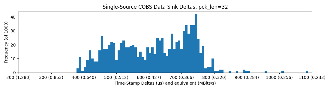
pyserial -> USB -> RP2040 Earle Core SDK USB
Overclocking the RP2040 to 240MHz does help, organizing the distribution into a tighter spike at the fast end:
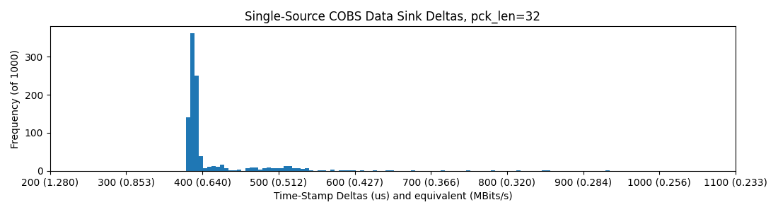
pyserial -> USB -> RP2040 @240MHz Earle Core SDK USB
USB Serial: SAMD21
And the SAMD21, at 48MHz clock, does much worse (notice the stretched axis):
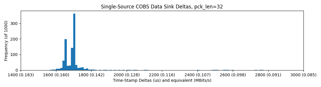
pyserial -> USB -> SAMD21 XIAO
All in, these results were dissapointing, so I elected to circle back with the Teensy 4.0, a 600MHz bad-boy that advertises a 480Mbit/sec USB implementation.
USB Serial: Teensy 4.0
OK, these were all upsetting and I tested Ethernet and the PI next, but then I circled back to try the Teensy, since I think that Paul is an absolute wizard and I know that his Teensy core is spectacularly well engineered - I was actually not dissapointed:
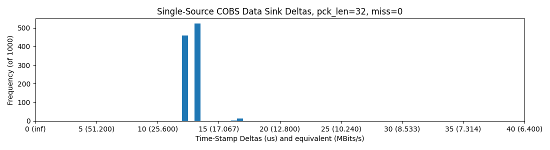
Pyserial -> USB -> Teensy 4.0, with 32 Byte Packets (note the x-axis change)
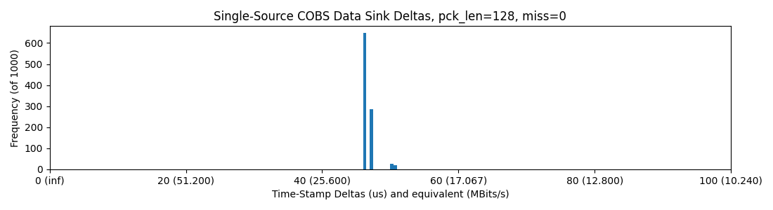
Pyserial -> USB -> Teensy 4.0, with 128 Byte Packets
This is wonderful - and a relief honestly, I wish I had tried it earlier. We are up to, easily, our spec of 5 Mbit/sec, and then well past it. Those deltas are wild: tens of microseconds.
Ethernet
python -> Ethernet -> Switch -> Ethernet -> WizNet -> SPI -> RP2040
Eyeing that sweet sweet 100/10 Ethernet link, I collected the WizNet W5500-EVB-PICO, (an RP2040 Pico with the Wiz strapped on) and connected it to my PC.
A few notes on this setup; (1) the Wiz connects to the RP2040 via SPI, which (as we will see later) means we are basically SPI bottlenecked, in addition to the Ethernet’s own packet time, etc. (2) we connect via a switch to our local network, i.e. our PC. So, the setup goes from the RP2040, over SPI to the Wiz, over Ethernet to a switch, back over Ethernet to our PC.
Setting this up also required some static IP configuration: in Windows, I configured the Ethernet interface to have a static IP on the local network, and configured the RP2040 to aim packets at the same (it also got a static IP).
So, the results:
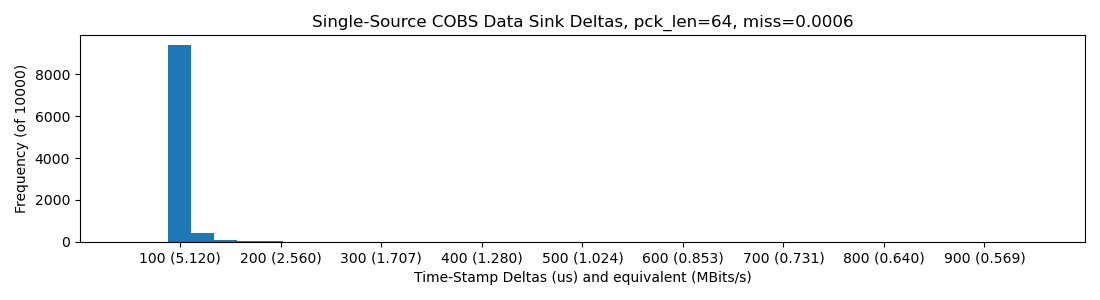
RP2040 -> WizNet -> Ethernet -> Switch -> Ethernet -> PC; one-way, Python ingesting.
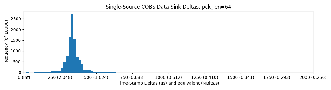
RP2040 -> WizNet -> Ethernet -> Switch -> Ethernet -> PC; round-trip (packets down and back up), Python, 64 Bytes / Packet
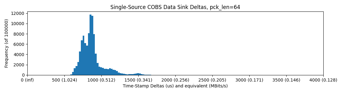
Ethernet does better than most USB here, and we can strap mega-sized packets through it. While packet size increases delay, total bandwidth goes up:
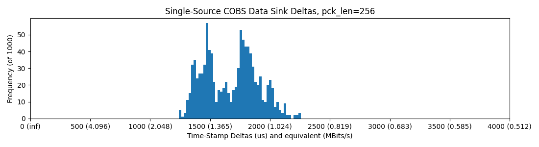
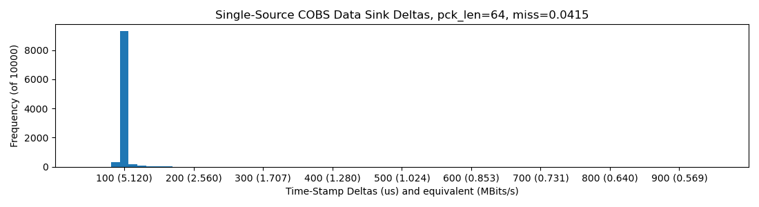
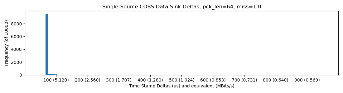
RP2040 -> WizNet -> Ethernet -> Switch -> Ethernet -> PC; round-trip (packets down and back up), Python, 256 Bytes / Packet
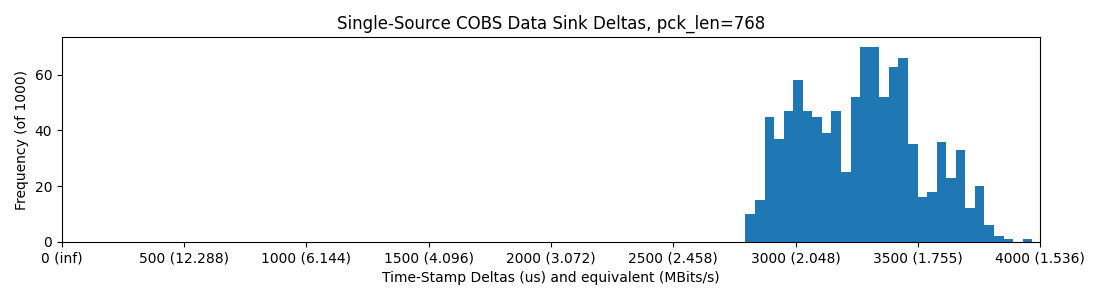
RP2040 -> WizNet -> Ethernet -> Switch -> Ethernet -> PC; round-trip (packets down and back up), Python, 768 Bytes / Packet
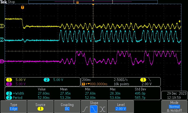
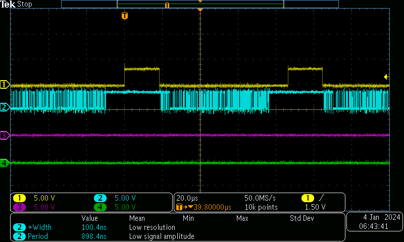
We still have a real bottleneck around 2Mbit/sec, much less than we would surmize on a “100Mbit” link, so what’s up? Well, if we look at the RP2040-to-WizNet SPI link on the scope, we get a sense:
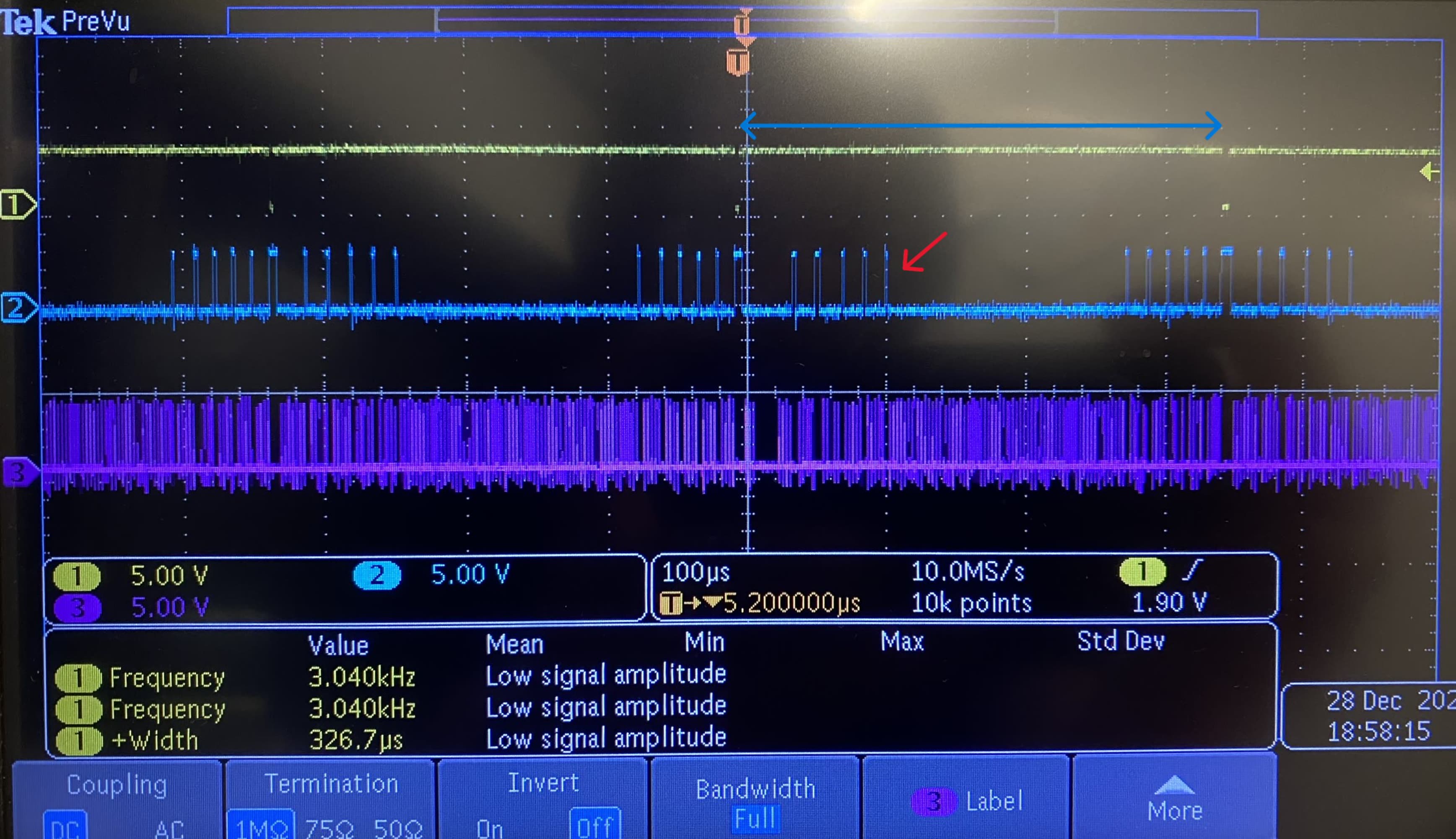
CH1: Transaction Flag, CH2: Chip Select and CH3: CLK - we can see that the single Ethernet transaction is made of multiple SPI transactions between the RP2040 and the Wiz…
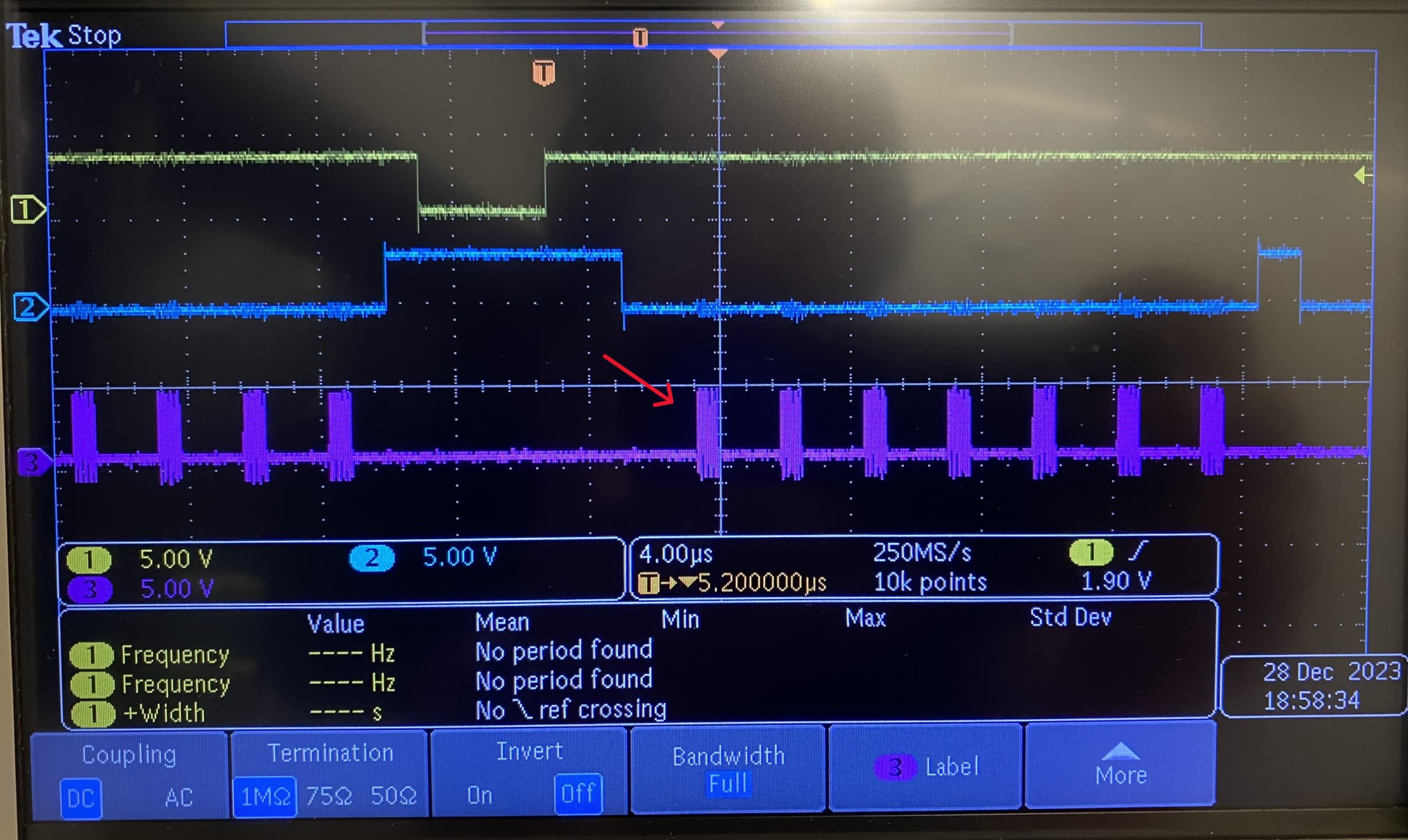
CH1: Transaction Flag, CH2: Chip Select and CH3: CLK - … and that within each transaction, the actual data transfer (on CH3, where the CLK is active) are pretty well spaced out!
I.E. even though we are running 12.5MHz SPI to our 100Mbit Ethernet device, whatever in-between is happening (the Arduino Ethernet library, on top of abstracted SPI interfaces, etc etc) is introducing up to 5x overhead, so we are left with tops 2Mbit/sec of real data rate.
Raspberry Pi, and SPI
RPi 4 -> ? / SPI -> RP2040 Hardware SPI SDK
Given that the WIZ communicates to the uc via SPI anyways, I thought I would hook it up directly. Being able to do this is basically what SBC’s are for anyways (their CPU cores having direct access to some GPIO, just like an MCU).
This has the caveat that we are now in-context on this SBC (rather than, i.e, our beefy-ass laptop with a hella GPU), but maybe we need this middle ground. So, the setup is: RP2040 via SPI directly to the RPi 4.
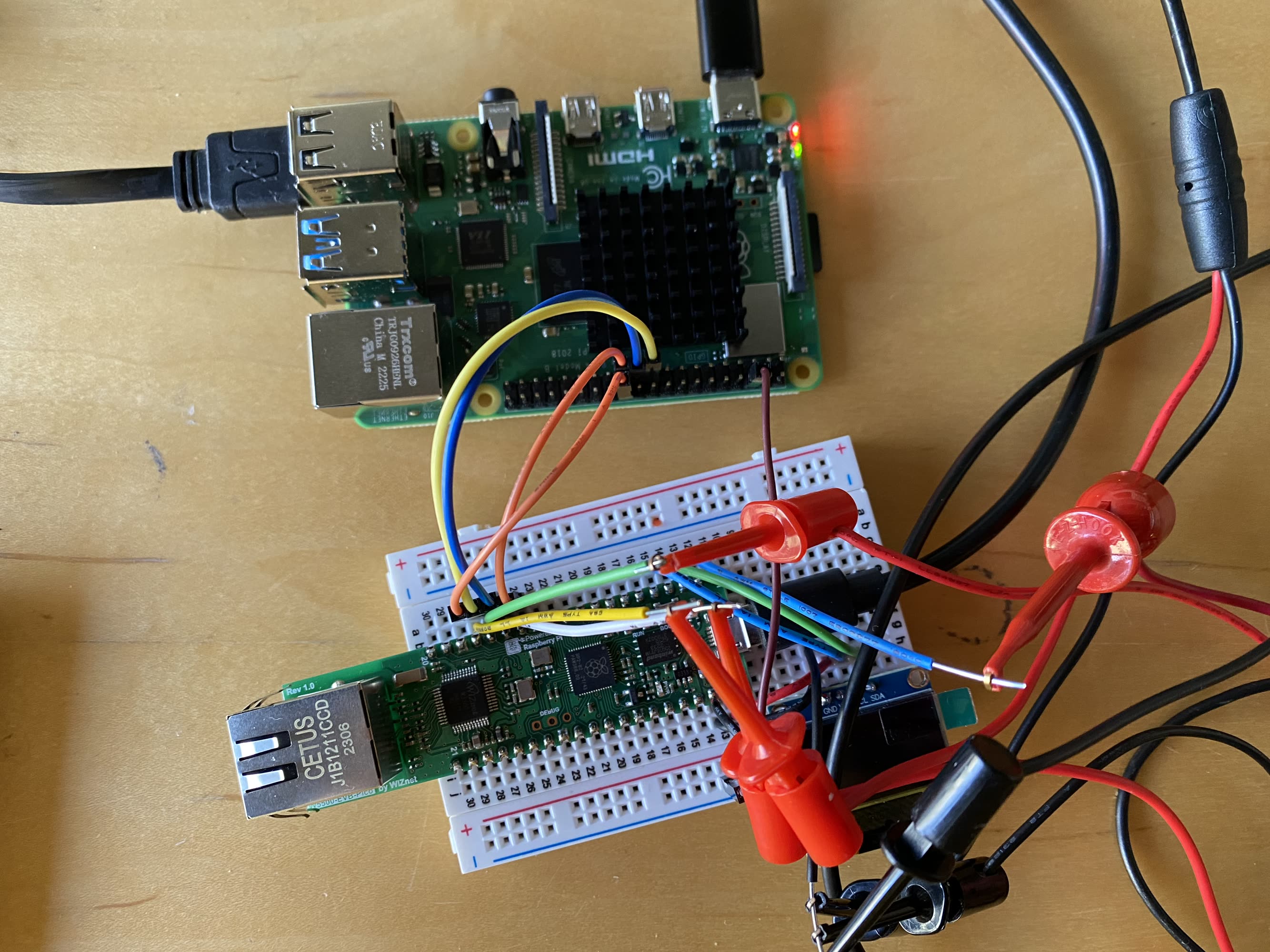
The RPI/SPI Setup…
About the TTL levels here, traces look solid up to around 20Mbit, where I suspect we would genuinely loose some bits in the PHY:
At 20MHz, we start to see some shaky TTL…
In any case, this tests pretty well. In these cases, we are “transacting” - SPI out begets SPI in - and counting bytes that are out-of-sequence (missed). IIRC, I did all of these tests at 240MHz on the RP2040, to help with ISR time.
RP2040 @ 240MHz -> SPI -> RPi 4 Python w/ spidev: 10Mbit/sec
10Mbit underlying rate gets us into 5Mbit of realized bandwidth, which at this point was some great news for me. It falls off of a cliff after this though (check the missed-bytes ratio in the plot titles), probably the MCU running out of time to service ISRs:
RP2040 @ 240MHz -> SPI -> RPi 4 Python w/ spidev: 11Mbit/sec
RP2040 @ 240MHz -> SPI -> RPi 4 Python w/ spidev: 15Mbit/sec
We also come up against a bandwidth limit around 5Mbit. There’s an observable delay between transmissions on the line, around 10us, which is the RPi chunking between python loops. It would sometimes stretch to 50us or so…
10Mbit/sec, CH: Chip Select, CH2: DO
But, all-in, SPI-direct is a promising approach, or the best performing so far: it shows big bandwidth and small loop times, I mean, that’s 100us period for cyclic transactions on these plots, which is killer, that’s potential for 10KHz of action (if we can hook everything else up…) between a Python process on a decent-sized CPU and some embedded worlds.
What’s the Point ?
Latency and Throughput Both Matter
When we’re building machines, robotics, or whatever mechatronic devices, we are always interested in how fast we can get data into- and out-of the world; see also our Ring Test Page where we track how fast we can get between an MCU’s computer-part and its physical-part (the pins). In most systems, we are interested in pure throughput, but with machines are interested in both: data freshness as well as total data per second. Given that most “off-the-shelf” links report just their maximum throughput and not latencies, or actually-realized throughput, I thought it wise to test.
Many Links are Not As Advertised
I started doing these tests because I wanted to sanity check the USB link, which I assumed to be easily within range of 5Mbit/sec, given that USB 2.0 operates at 12Mbit/sec, and I was dead wrong. So, that’s a lesson learned: measure your systems.
This is because we normally talk about a link’s “underlying speed” when we discuss; it’s easy to measure how long it takes for one bit to be transmitted. However, with all of the rest of the framing (software on either end, protocol, etc), measurements get messier.
Even the Teensy’s USB Serial, which is wonderful compared to the rest, gives us 20Mbit/s on top of a 480Mbit/s link (others use, AFAIK, the 12Mbit/s USB spec).
For a common-day example of this, observe that most SD cards advertise above 80MB/sec, but we typically see ~ 20MB/sec in practice.
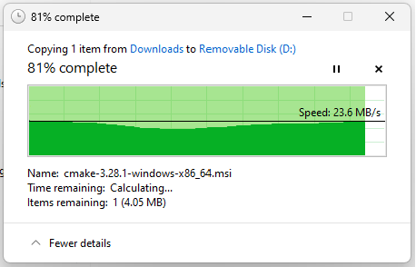
Even on (what I assume to be) a highly optimized system: an SD card (80Mbit/sec advertised rate) plugged directly into my XPS 15’s SD card reader, we only realize, normally, 1/4 of that rate.
Simple and Device-Specific
I also had a bias of mine confirmed (so, beware the validity of this statement); simple, low-level systems, custom-built, often out-perform fancy, layers-of-abstraction codes. In embedded, where we all want to have portable code, but basically can’t really, this feels especially true. It’s also not that difficult to (for example) spin up a UART or a SPI peripheral from scratch, it’s just a rare expertise.
This also means that many of the results above could be improved with other folks’ better code, though I’ve started with what I can tell to be the best in the open-source business. There is a larger point to be made here about open source ecosystems vs. code portability vs. performance; the gist of which being that device-specific engineering is typically the route to performance, but the open hardware community is focused (at the moment) on trying to make code portability work in embedded systems (see Arduino and Micro/Circuit-Python, for example). IMO, this is not the way, but I will discuss that at more length at some other time.
Interrupt Handling is Often the Bottleneck
This is something I’ve seen again and again: we aren’t really bandwidth limited when we use simple embedded links: UART and SPI, for example. The drivers can drive it, the rx’ers can catch it, and the noise is “not so bad”. Under heavy loads, though, we become limited by the time it takes for our MCU to service the associated interrupts.
This has another hairy connotation for open hardware: it means that, “normally,” we need to know how hard the MCU is going to be working before we can appropriately engineer the networking links. If the MCU is terribly busy handling SPI comms to a sensor, then we come along and ask it to please deliver those data over a network link at some absurd rate, we may very well lock it up, miss some readings, or miss some packets. So! More trouble for layer-agnosticity.
What Next ?
(1) These codes are not optimal (implementations) and might be worth trying again with more focus/time, esp. the RP2040 PIO, which seemed so promising to me. Also the WizNet SPI library could probably be done up all-fancy like, to delete some of that blank time.
(2) We can/should have more-better high level protocols (CRC, flow control, perf measuring) for these “generic” low-level interfaces (SPI, UART) that would make it easy to bootstrap new MCUs, and promote their peripherals to proper link layers. A goal of that development should be that they can auto-test themselves routinely, so that we can do this kind of work in-situ.
(3) There are many more to test: Teensy’s Ethernet implementation probably rippeth, the SAMD51 (another favourite MCU of mine), the ever-popular ESP32’s Bluetooth and WiFi links, etc etc.
That’s all for this one, TTFN.
« Searching for the Commons of OSHW
Delete Your '\n' Delimited Firmware Interface! »